
Owner's manual


7
not to scratch the inside walls of the seal groove or the
edge of the Piston with the wire hook.
2. Clean out the seal groove. Place a new U-Cup Lip
Seal into the groove. Make sure the lips is not twisted
in the groove and the lips face the top of the Stapler
See the sketch below.
3. Carefully wipe off the U-Cup Lip Seal surface with a
clean rag and lubricate it generously with Pneumatic
Light Air Tool Oil lubricant.
Return Cylinder U-Cup Lip Seal (#17):
1. Use a bent paper clip or pick to remove the old
U-Cup Lip Seal from the internal seal groove inside
the Return Cylinder. Be careful not to scratch the
inside walls of the seal groove with the wire hook.
2. Clean out the seal groove. Place a new U-Cup Lip
Seal into the groove, be sure it is not twisted in the
groove. Be sure the lips are facing the inside of the
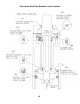
Return Cylinder as shown in the schematic (page 10-
11, 13).
WARNING: The U-Cup Lip Seals (#3) and (#4) look
alike, but they are diff erent, DO NOT mix them up.
3. Carefully wipe off the Lip Seal surface with a clean
rag and lubricate it generously with Pneumatic Light
Air Tool Oil lubricant.
Piston Rod U-Cup Lip Seal (#5):
1. Remove the old U-Cup Lip Seal from the seal
groove with a bent paper clip or pick using care not
to scratch the inside walls of the seal groove with the
wire hook.
2. Clean out the seal groove and install a new U-Cup
Lip Seal. Be sure the Lips are facing the right direction
and are not twisted in the groove. See the sketch
below.
WARNING: The Lip Seals (#3) and (#4) look alike, but
they are diff erent, DO NOT mix them up.
3. Carefully wipe off the seal surface with a clean rag
and lubricate it generously with Pneumatic Light Air
Tool Oil lubricant.
Plunger Wiper Metal Cap O-Ring (#4):
1. Use a bent paper clip to pick out the felt Wiper
Seal out of its groove in the Body Cap (#2).
2. Clean out the groove and insert the new O-Ring
(#6) in to the groove in the metal body cap (#2).
Return Cylinder O-Ring Gasket (#11):
1. Place a new O-Ring Gasket in the groove on top of
the Return Cylinder when you reassemble the Driving
Blade Assembly.
2. Wipe off the O-Ring Gasket seal surface and
lubricate it generously with Pneumatic Light Air Tool
Oil lubricant.
REASSEMBLING THE Stapler:
1. Be sure the Rubber Seat, Support Ring and
Cylinder are installed in the Body and are facing the
correct way.
2. All seal surfaces must be clean and lubricated
generously with Pneumatic Light Air Tool Oil lubricant.
Replace any part that shows signs of wear.
3. Use care when installing the seals into their respective
cavities. Be sure the Seals are contained in their
groove and do not come out as the parts slide together.
Generous cavity lead in chamfers have been provided to
help Seal installation.
4. Carefully insert the Piston Rod into the return Cylinder
and screw the Piston onto the rod. Be sure the Piston is
facing the correct way, ears up, hex down.
5. Assemble the Driving Blade, Dowel Pin and Jam Nut
on to the Piston Rod.
6. Insert the Driving Blade Assembly up into the bottom
of the Stapler Body Cylinder.
7. Be sure there is a new O-Ring Gasket in the top
groove of the Return Cylinder.
8. Insert the Plunger into the top cavity of the Body.
Line up the holes and install the three Plunger retaining
screws. It is important that the three #10-32 screws are
tight or air leakage will occur. Our recommendation is to
use 1-2 drops of blue Loctite® or similar on the 3 screws.
9. Install the Body Cap and Plunger Rubber Cap.
10. Turn the Stapler upside down. Install the Rubber
Bumper, Staple Channel Assembly and Adapter Foot. Be
sure to align up the Driving Blade with the slot in the Foot
before the Stapler is closed up.
11. NEVER FIRE THE Stapler WITHOUT THE RUBBER
BUMPER INSTALLED, IT WILL DAMAGE THE Stapler.
TO CLEAR A Staple JAM:
1. It helps to tap the Driving Blade back to the retracted
position before trying to remove a jammed staple. A
spare Driving Blade works best for this.
2. Try to pull the jammed staple out of the gate with a
pair of long nose pliers. If this does not work remove the
four (4) cap screws holding the Foot, Gate and Staple
Channel Assembly together.
3. Separate the Foot and gate with a screw driver just
enough to clear out the jammed staple.
4. Put thread locking compound on all screws and
reassemble the components.
OPERATING INSTRUCTIONS, continued
For Step-by-Step Videos and Instructions,
Visit our Web Site at: www.Powernail.com