INSTRUCTION MANUAL 24 inch Two Stage Gas Snow Thrower Model # DB7624E Have product questions or need technical support? Please feel free to contact us! Website: www.Amerisuninc.com www.PowerSmartUSA.com Toll free: 1-800-791-9458 Mon-Fri 9-5 EST Email: support@amerisuninc.
Technical data…...………………………………………………………... Introduction………………………………………………………………. Safety information…….………………………………………………... Knowing your snow thrower…………………………………………… Assembly and adjustments……………………………………………... Snow thrower preparation…....………………………………………… Operating your snow thrower...…………………………………………. Maintenance……………………………………………………………... Storage & Cleaning…………...…………………………………………. Troubleshooting…………………………………………………………. Exploded view and parts list……………………………………………...
INTRODUCTION Thank you for purchasing a PowerSmart® Product. This manual provides detailed information regarding the safe operation and maintenance of this product. Every effort has been made to ensure the accuracy of the information in this document. PowerSmart® reserves the right to change this product and specifications at any time without prior notice. Please keep this manual available to all users during the entire life of the product.
TRAINING Read, understand, and follow all instructions on the machine and in the manual(s) before attempting to assemble and operate. Keep this manual in a safe place for future and regular reference. • Be familiar with all controls and their proper operation. Know how to stop the machine and disengage them quickly. • Never allow children under 14 years of age to operate this machine.
PERSONAL SAFETY • Engine exhaust, and certain vehicle components contain or emit chemicals known to cause cancer, birth defects or other reproductive harm. • Read, understand and follow all instructions on your snow thrower unit and in this instruction manual before attempting to assemble and operate your machine. • Keep this instruction manual in a safe place for future and regular reference.
• Never over fill fuel tank. • Replace gasoline cap and tighten securely. • If gasoline is spilled, wipe it off the engine and equipment. Move machine to another area. Wait 5 minutes before starting the engine. • Never store the machine or fuel container inside where there is an open flame, spark or pilot light (e.g. furnace, water heater, space heater, clothes dryer etc.). • Allow machine to cool at least 5 minutes before storing.
• Plan your snow-throwing pattern to avoid snow discharge towards windows, walls, cars etc., thus avoiding possible property damage or personal injury caused by a ricocheting debris. • Never direct discharge at children, bystanders and pets or allow anyone in front of the machine. • Do not overload machine capacity by attempting to clear snow at too fast of a rate…. Remember! Slow and steady operation is best to avoid clogs of snow being impelled too rapidly.
• • • • • • • • • • • • • • Check bolts and screws for proper tightness (EVERY TIME before & after use) as engine vibration could cause hardware to loosen…consider using a Loc-Tite product to keep hardware secure. This process will keep the machine in safe working condition. Also, visually inspect machine for any damage. Verify that the auger gearbox, located between your right and left auger blades, has substantial lubricant in the casing.
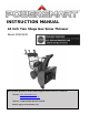
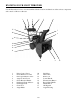
KNOWING YOUR SNOW THROWER Use the illustrations below to become familiar with the locations and functions of the various components and controls of this snow thrower.
19 20 19 20 21 22 Fuel Tank Cap Primer Bulb 21 22 Switch Key Choke Lever Drive Control Lever Located on the right side of the upper handle, the Drive Control Handle is used to engage and disengage the drive wheels. Squeeze the Drive Control Handle against the upper handle to engage the wheels; release to disengage. Drive Speed/Gear Control The Speed/Gear Control is located on the center of the panel and is used to set the drive speed and direction of travel.
ASSEMBLY AND ADJUSTMENTS The following section describes steps necessary to prepare the snow thrower for use. If after reading this section, you are unsure about how to perform any of the steps please call (800) 791-9458 Mon-Fri 9-5 EST for customer service assistance. Failure to perform these steps properly can damage the snow thrower. Unpacking Unpack the snow thrower and all its parts, and compare against the list below. 1. Snow Thrower 2. Discharge Chute Assembly 3. Chute Rotation Handle 4. (Qty.
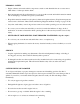
4. Cut and remove all tie wraps that are on Cables, Frame Handles, Drive Control (Lever) & Auger Control (Lever). 5. Verify that the connection for the Upper & Lower Drive/Auger Cables is accurate. (See Figure 2) Figure 2 Step 2:Installing the Chute Assembly 1. When installing the Chute Assembly, please note that the Chute Deflector Cable will be pre-attached to the Upper Handle. 2.
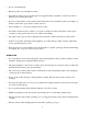
2. Attach Chute Handle to base of Chute Gear Connection and secure with Cotter Pin, as indicated on Figure 5. Figure 5 3. Verify that ALL cables are clear and not obstructing the Chute Handle operation of your snow thrower unit. (See Figure 6) Figure 6 Step 4 – Skid shoes installation and adjustments 1. Locate the set of skid shoes from parts bag and remove the bolts. 2. Loosely install the skid shoes using the bolts and hex nuts as shown on each side of the auger housing.
SNOW THROWER PREPARATION PLEASE REFER TO ENGINE MANUAL (SEPARATE DOCUMENT) FOR ENGINE OPERATION INSTRUCTIONS. The following section describes steps to prepare your snow thrower for use. If after reading this section, you are unsure about how to perform any of the steps please call 1-800-791-9458 for customer service. Failure to perform these steps properly can damage your snow thrower or shorten its life expectancy.
AUGER AND DRIVE CONTROLS 1. To engage the auger (blades), press down on the auger control lever (left side handle). 2. To engage the drive, press down on the drive control lever (right side handle). The machine should start moving in the direction and speed for the respective setting on the speed/gear control. 3. When finished clearing a snow path, release the auger control lever (handle) and the drive control lever (handle).
OPERATING YOUR SNOW THROWER STARTING Please refer to ENGINE manual (separate document) for engine operation instructions. CLEARING SNOW Start the engine (see ENGINE manual) once your snow thrower has been running outside for several minutes, it is now ready for use. Make sure the path in front of your Snow Thrower is free from people, animals, objects, and all other obstructions except for snow. Adjust the chute outlet to the desired direction.
MAINTENANCE WARNING! Never perform maintenance while your snow thrower is running. Turn OFF the engine before performing any maintenance tasks on your Snow Thrower. Proper maintenance of your snow thrower will help prolong its life. Please perform the following maintenance procedures as required. Please read the ENGINE manual for engine maintenance procedures. Do not attempt to repair your snow thrower unless you have the proper tools and instructions for disassembly and repair.
4. Wait until the auger and impeller have come to a full stop. 5. Clear any visible jams using the clean out tool attached to your machine. WARNING! DO NOT try to clear jams with your hands or feet. AUGER SHEAR PINS REPLACEMENT Shear pins are used to attach the auger shaft to the auger blades. A clog or jam in the augers may cause one or multiple shear pins to break. The shear pins are a safety mechanism and designed to break under high load or impact and protect the auger drive system from damage.
middle position between these two settings is neutral (there is no actual neutral "notched" position on the control panel). 1. With the engine running engage the drive control handle and move the speed control lever between 1 and R1 to determine which way the cables need to be adjusted. Release the drive control handle when shifting between gears. 2.
AUGER BELT INSTALLATION WARNING! Entanglement Hazard – Before performing any service procedures, make sure the engine is off and remove the spark plug wire from the spark plug to ensure the engine cannot accidently start. 1. Push the auger tension pulley arm to move the auger brake to allow access for installation of the belt into the auger pulley. 2.
• Misaligned tension pulley, the pulley should move parallel to the belt centered to the belt • Check return spring operation and tension Inspect the auger control lever (handle) and cable: • Cable and connection damage • Free movement (from engage to disengaged positions) • Binding or improperly routed cable • Cable pulley(s) damage, misalignment and binding • Cable adjustment plate damaged or improper installation • Handle damaged or binding at pivot STORAGE & CLEANING PROPER STORAGE PROCEDURES WARNING!
TROUBLESHOOTING Problem Causes Remedy WARNING - Before attempting to make any inspections, repairs or adjustments, stop the engine, wait for all moving parts to stop moving and carefully disconnect the engine spark plug wire. If tipping or turning the snow blower is required for any inspection or repair, first wait until the engine is cool to the touch and then drain the engine of all fuel and oil into suitable containers and store or dispose of in a proper manner.
Problem Causes Remedy Drive system No forward or reverse drive movement when drive handle engaged Drive speed control stuck in gear or won’t change gears Drive speed control allows only 1 direction Drive engaged when drive control handle released Auger System Auger not rotating when auger control handle engaged or Not blowing snow or Poor snow blowing performance Check drive belt tension pulley for damage or incorrect tension, repair as necessary. Replace drive belt.
Problem Auger System Auger belt broken, or repeated failure Auger rotating when auger control handle released Causes Remedy Auger tension pulley arm return spring broken or missing Replace tension arm return spring Auger tension pulley arm stuck or binding Repair or replace tension arm as necessary Auger tension pulley arm or pulley misaligned or damaged Repair, replace or align tension arm and or pulley as necessary Foreign material on pulleys and belt, oil, grease, dirt etc.
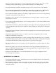
EXPLODED VIEW AND PARTS LIST Panel Assembly (All Parts Number Begin with P) Item Stock # 1 Description Qty Item Stock # Description Qty 303020240 Flange Screw M8×20 4 19 303020275 Flange Screw M8x40 4 2 303080530 Lower Handle 1 20 303042013 Flat Washer 8 4 3 303030026 Nut M8 4 21 303043010 Saddle Washer 8 4 4 203020865 Knob 4 22 303030036 locknut M8 4 5 303043010 Saddle Washer 8 4 23 203050373 Operation Panel 1 6 T-screw M8X55 4 24 2 Rubber Washer 1 25
Chute Assembly (All Parts Numbers Begin with C) Item Stock # Description Qty Item Stock # Description Qty 1 303020275 Bolt M8x40 2 21 303130339 Clip 1 2 303041022 Spring Washer 8 2 22 Cutter Pin 1 3 303042023 Flat washer 8 2 23 303160737 303050032 Snap Ring 13 1 4 303080523 Support Tube 1 24 303042130 Flat Washer 13 1 5 303010176 203010820 Screw 3 25 303010270 Screw 4x14 2 Discharge Chute Seat 1 26 203010825 Steering Gear Cover 1 303030087 303180953 loc
Frame Assembly (All Parts Number Begin with F) 28
Item Stock # Description Qty Item Stock # Description Qty 1 303122002 Dowel Pin 2 46 Wheel Assembly Spacer Bush Closing Ring 2 47 Flat Key Small Synchronous Pulley 2 48 303060060 Bush 1 4 302090217 203050140 303050028 303110014 303060041 1 2 1 49 303160140 303110022 303123008 Big Gear Woodruff Key Elastic Cylindrical Pin 1 1 1 50 51 52 303160432 303020154 303130094 Screw Square Neck Bolt M8x40 Small Tension Spring 1 5 6 7 303160191 Spacer 8 303170016 Wheel Shaft 1
Auger Housing Assembly (All Parts Number Begin with H) 30
Item Stock # Description Qty Item Stock # Description Qty 1 303020245 Flange Screw M8x14 6 29 303030076 Nut M8 3 2 303070234 Bearing Housing 2 30 303070929A 1 3 203060013 Plastic Bearings 2 31 303020542 4 203050109 Spacer 4 32 303180952 5 203060012 Flange Bushing 8 33 303020166 24-inch Shave Plate Square Neck Bolt M8X18 Auger Housing Assembly Square Neck Bolt M8x18 6 303180424 Auger Assembly R 2 34 303070197 Skid Shoe 2 7 203050108 Spacer 6 35 302130005
TWO (2) YEARS LIMITED WARRANTY PowerSmart is committed to building tools that are dependable for years. Our warranties are consistent with our commitment and dedication to quality. TWO (2) YEARS LIMITED WARRANTY OF POWER SMART PRODUCTS FOR HOME USE. PowerSmart (“Seller") warrants to the original purchaser only, that all PowerSmart consumer power tools will be free from defects in material or workmanship for a period of two (2) years from date of purchase.