INSTRUCTION MANUAL 20" 3-in-1 Self Propelled Lawn Mower Model # DB8620 Have product questions or need technical support? Please feel free to contact us! Website: www.Amerisuninc.com www.powersmartusa.com Toll free: 1-800-791-9458 Mon-Fri 9-5 EST Email: support@amerisuninc.
CONTENTS Technical data…...………………………………………………………... Introduction………………………………………………………………. Safety information…….………………………………………………... General safety procedures ……....……………………………………… Important safety instructions……………………………………………. Knowing your lawn mower……………………………………………… Lawn mower preparation………………………………………………... Operation……………………....………………………………………… Maintenance……………………………………………………………... Storage……………………………………………………………………. Troubleshooting………………………………………………………….
INTRODUCTION Thank You for Purchasing a PowerSmart® Product. This manual provides information regarding the safe operation and maintenance of this product. Every effort has been made to ensure the accuracy of the information in this manual. PowerSmart® reserves the right to change this product and specifications at any time without prior notice. Please keep this manual available to all users during the entire life of the lawn mower.
GENERAL SAFETY PROCEDURES For any questions regarding the hazard and safety notices listed in this manual or on the product, please call (800) 791-9458 Mon-Fri 9-5 EST before using the engine. DANGER: CARBON MONOXIDE Using an engine indoors CAN KILL YOU IN MINUTES. Engine exhaust contains carbon monoxide (CO). This is a poison gas you cannot see or smell. If you can smell the engine exhaust, you are breathing CO. But even if you cannot smell the exhaust, you could be breathing CO.
IMPORTANT SAFETY INSTRUCTIONS General Operation Read, understand, and follow all instructions on the machine and in the manual(s) before starting. 1. Do not put hands or feet near or under the machine. Keep clear of the discharge opening at all times. 2. Only allow responsible adults, who are familiar with the instructions, to operate this machine. 3. Clear the area of objects such as rocks, wire, toys, etc., which could be thrown by the blade. Stay behind the handle when the engine is running. 4.
4. Use extra care when approaching blind corners, shrubs, trees, or other objects that may block your view of a child. Service 1. Safe Handling of Gasoline 2. To avoid personal injury or property damage, use extreme care in handling gasoline. Gasoline is extremely flammable and the vapors are explosive. 3. Extinguish all cigarettes, cigars, pipes, and other sources of ignition. 4. Only use a US EPA approved compliant portable fuel container. 5. Never remove gas cap or add fuel with the engine running.
KNOWING YOUR LAWN MOWER Please use the illustration below to familiarize yourself with the location and function of the components that control of your lawn mower.
LAWN MOWER PREPARATION The following section describes steps necessary to prepare the lawn mower for use. If after reading this section, you are unsure about how to perform any of the steps please call (800) 791-9458 Mon-Fri 9-5 EST for customer service. Failure to perform these steps properly can damage the lawn mower or shorten its lifespan. UNPACKING Unpack the lawn mower and all its parts, and compare against the list below.
ATTACH THE FRONT WHEEL ASSEMBLY The front wheel assembly attaches to the front of the deck. To attach the front wheel to the deck, perform the following steps: 1. Mount the single wheel to the wheel bar with the mounting screw. 2. Attach front wheel and bar assembly to the deck with four M6 screws, four washers and four M6 nuts. M6 Screw ATTACH LOWER & UPPER HANDLE 1. Take lower handle and line up the hole in the lower handle with the hole on the handle bracket. 2.
GRASS CATCHER Attach grass catcher 1. Lift mower rear discharge door. 2. Place grass catcher into the slots in the handle brackets. 3. Release the rear discharge door so that it rests on the grass catcher. Caution: Make sure that the mulch plug adapter has been removed from of the rear deck door’s opening. Remove grass catcher 1. 2. 3. 4. Lift mower rear discharge door. Lift grass catcher up and off the slots in the handle bracket. Slide the mulch plug into the ejector opening.
ADJUSTING THE CUTTING HEIGHT Warning! Cutting height adjustments should only be performed after the engine and blades have come to a complete stop! It is always best to begin cutting your lawn with a higher deck height to prevent scalping your lawn. Rear wheel The cutting height for the rear wheels is adjusted with a single lever. Actuate the adjustment lever and pull it to the required position. Please make sure that the lever locks into position.
ENGINE START/STOP LEVER Engine start/stop lever This lawn mower comes equipped with an engine start/stop lever to prevent unintentional starting and to ensure safe operation. Releasing this lever will quickly stop the blade in case of danger. The lever must be actuated before the lawn mower is started. When the engine start/stop lever is released, it must return to its initial position.
It’s import to keep the underside of the mower deck clean and remove grass build-up. This buildup will decrease mulching quality, and make it harder for the equipment to bag the grass. Always mow along inclines (not up and down). You can prevent the lawn mower from slipping down by holding a position at an angle upwards. Select the cutting height according to the length of the grass. If necessary, mow a number of times so that you never cut more than 2 inches of grass in one go.
MAINTENANCE Proper routine maintenance of this mower will help prolong the life of the machine. Always observe safety rules when performing any maintenance. The warranty on this lawn mower does not cover items that have been subjected to operator abuse or negligence. To receive full valve from warranty, operator must maintain the lawn mower as instructed here. Changing of engine-governed speed will void engine warranty. All adjustments should be checked at least once each season.
RECCOMENDATIONS FOR OFF SEASON STORAGE CAUTION: Never place any type of storage cover or tarp on the MOWER while it is still hot. If the MOWER is being stored for short periods of time (30 to 60 days), add stabilized fuel to the gas tank until it is full. Run the engine for 2 – 3 minutes allowing stabilized fuel mixture to circulate through the carburetor. NOTE: Keeping the fuel tank full, reduces the amount of air and vapor and helps reduce deterioration of the fuel.
TROUBLESHOOTING Problem Engine fails to start Engine runs erratic. Engine overheats. Idles poorly. Excessive vibration/noise Mower will not mulch grass. Uneven cut. Cause Engine start/stop lever disengaged. Spark plug wire disconnected. Fuel tank empty or stale fuel. Engine not primed. Faulty spark plug. Blocked fuel line. Engine flooded. Spark plug wire loose. Blocked fuel line or stale fuel. Water or dirt in fuel system. Dirty air filter Engine oil lever low. Air flow restricted.
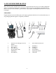
EXPLODED VIEW AND PARTS LIST Handle Assembly Item Stock# 1 303080465 2 303070984A 3 302020019A 4 303080466 5 303020502 6 303030032 7 303200099 8 303160531 9 303030065 10 303030025 11 303230014A 12 303042116 Description Qty Engine control lever 1 Upper handle 1 Sponge foam 1 Drive control bar 1 Bolt M6x35 1 Nylon nut M6 2 Cable rubber plug 1 Rope hook 1 Nut M6 1 Cover type nut M6 2 Handle lock lever 2 Flat washer 8 2 Item 13 14 15 16 17 18 19 20 21 22 23 24 18 Stock# 303160611A 303010269 303070983A 30303
Deck Assembly Item 1 2 3 4 5 6 203050346A Rear cover shaft 1 24 303020163 7 8 9 10 11 203050345A 303190222 303070980A 303042011 303010108 1 1 1 3 3 25 26 27 28 29 203050342A 303160423 303030087 303010322 202270003A Description Flat washer Washer 8 Bolt M8x35 Driving pulley Woodruff key Square neck bolt M6x25 Belt cover Flat washer Nylon nut Screw ST4x14 Blade holder 1 30 303110012 Key 4.
Drive Assembly Item 1 2 3 4 5 6 7 8 9 Stock# 203050344A 303030036 203040021A 203010806A 303160470 303060104A 303020468 303020276 303060115 10 203050340 11 203050341A 12 303180892A Description Qty Wheel cover 2 Nylon nut M8 2 Wheel 2 Dust cover 2 Gear Right 1 Adjustment plate 1 Hexagon bolt 2 Hexagon bolt 2 Rear axle ring 2 Height adjustment 1 handle Height adjustment 1 lever Rear axle assembly 1 Item 13 14 15 16 17 18 19 20 21 20 Stock# 303020339 303130322 302040067 303160607A 303240487A 30312301
Front Wheel Assembly Item Stock# Description Qty Item 1 303020503 Bolt M6x35 3 11 2 303020282 Bolt M6x16 1 12 3 303041009 Spring washer 6 1 13 4 5 6 7 303042021 303070978 303060108 303070977A 1 2 1 1 14 15 16 17 8 303100071 2 18 203020865A Knob 1 9 10 303030032 303042021 Flat washer 6 Mounting plate Bearing bracket Front wheel support Ball bearing 61902-2Z Nylon nut M6 Flat washer 6 Description Square neck bolt 303020167 M6x36 303160617A Front wheel stents Square neck bolt 3
TWO (2) YEARS LIMITED WARRANTY PowerSmart is committed to building equipment that will provide years of dependable service. Our warranties are consistent with our commitment and dedication to quality. TWO (2) YEARS LIMITED WARRANTY OF POWER SMART PRODUCTS FOR HOME USE. PowerSmart (“Seller") warrants to the original purchaser only, that all PowerSmart consumer power tools will be free from defects in material or workmanship for a period of two (2) years from date of purchase.