INSTRUCTION MANUAL Electric Chipper Shredder Model # PS10 Have product questions or need technical support? Please feel free to contact us! Website: www.Amerisuninc.com Toll free: 1-800-791-9458 M-F 8-4 CST Email: support@amerisuninc.
CONTENTS Technical data…...………………………………………………………... General safety rules…….………………………………………………... Specific safety rules for chipper shredder………………………………. Electrical information…………………………………………………... Knowing your chipper shredder………………………………………… Assembly and adjustments……………………………………………… Operation………………………………………………………………... Maintenance……………………………………………………………... Troubleshooting………………………………………………………….
GENERAL SAFETY RULES Safety is a combination of common sense, staying alert, and knowing how your chipper shredder works. SAVE THESE SAFETY INSTRUCTIONS. WARNING: To avoid mistakes that could cause serious injury, do not plug in the chipper shredder until the following steps have been read and understood. 1. READ and become familiar with this entire instruction manual. LEARN the tool’s applications, limitations, and possible hazards. 2. AVOID DANGEROUS CONDITIONS.
GENERAL SAFETY RULES (CONTINUED) 13. NEVER LEAVE A RUNNING TOOL UNATTENDED. Turn the power switch to OFF. Do not leave the tool until it has come to a complete stop. 14. NEVER STAND ON A TOOL. Serious injury could result if the tool tips or is accidentally hit. DO NOT store anything above or near the tool. 15. DO NOT OVERREACH. Keep proper footing and balance at all times. Wear oil-resistant rubber-soled footwear. Keep the floor clear of oil, scrap, and other debris. 16. MAINTAIN TOOLS PROPERLY.
SPECIFIC SAFETY RULES FOR CHIPPER SHREDDER WARNING: Do not operate your chipper shredder until it is completely assembled and installed according to the instructions. 1. 2. 3. 4. 5. 6. 7. 8. 9. Before starting the chipper shredder, make sure that the hopper inlet is empty. Keep your face and body away from the opening. Do not allow hands or any other part of the body or clothing near the hopper or discharge chute. Never put your hands into the hopper while the chipper shredder is running.
ELECTRICAL INFORMATION DOUBLE INSULATION Double insulation is a concept in safety in electric power tools that eliminates the need for the usual three-wire grounded power cord. All exposed metal parts are isolated from the internal metal motor components with protecting insulation. Double insulated tools do not need to be grounded. WARNING: The double insulated system is intended to protect the user from shock resulting from a break in the tool’s internal insulation.
ELECTRICAL INFORMATION (CONTINUED) Guidelines for using extension cords Make sure your extension cord is in good condition. When using an extension cord, be sure to use one heavy enough to carry the current your product will draw. An undersized cord will cause a drop in line voltage resulting in loss of power and overheating. The table below shows the correct size to be used according to cord length and nameplate ampere rating. If in doubt, use the next heavier gauge.
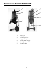
KNOWING YOUR CHIPPER SHREDDER 5 4 6 3 2 7 1 1 2 3 4 5 6 7 Power cord ON/OFF switch Overload protector Hopper locking knob Feeding chute / Hopper Housing cover Discharge chute 9
ASSEMBLY AND ADJUSTMENTS Unpacking (Fig. 2) Unpack the chipper shredder and all its parts, and compare against the list below. Do not discard the carton or any packaging until the chipper shredder is completely assembled.
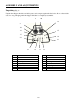
ASSEMBLY AND ADJUSTMENTS (CONTINUED) Tools needed for assembly • • Adjustable wrench Screwdriver 19 21 Setup the stand and attach wheels 20 1. Insert the end frame (20) into each hole of the two legs (19 & 21). 2. Position the axle tube (12) between the two legs (19 & 21). 3. Slide the wheel axle (10) through the hole in one of the legs (19) then through the axle tube (12) and out through the hole in the other leg (21). 4. Position the washers (14) and wheel spacer (11) on each end of the axle. 5.
7. Press the wheel covers into the wheels to cover the ends of the axles. You may use a hammer to seat them securely over the axles. 8. Lock the end frame (20) to 2 legs (19 & 20) using fixed screws (16). Attach the stand to shredder main body Turn the main body upside down, insert the two ends of the stand assembly into the housing.
OPERATION Starting Make sure the switch is in the OFF position. Plug the chipper shredder into a suitable outlet using an approved extension cord if necessary. Push the ON/OFF switch to “ON” to turn the chipper shredder on. Stopping Push the ON/OFF switch to “OFF” to turn the chipper shredder off. CAUTION: The chipper shredder will not operate if the hopper locking knob is loose. Hopper locking knob Overload protection Your chipper shredder is designed with overload protection.
1. Only insert as much material as to prevent blockage of the feeding funnel. Chop chipper waste that has been stored for a few days and is wilted and damp alternately with dry branches. This prevents the cutting blades from blocking up. Widely branched material with leaves must be completely chopped before new material is fed. Make sure that the chopped material can fall freely from the ejection slot. 2.
MAINTENANCE WARNING! Always wear gloves when cleaning. Cleaning chipper shredder 1. Unscrew the hopper locking knob counter clockwise and open the hopper. 2. Clean cutting blades and discharge area and remove wood sticks or objects that may clog the blades. 3. The chipper shredder has two blades that are attached to a rotary plate with two screws. Before any maintenance or cleaning is done on the blades, always turn the switch off and disconnect the plug from the power source. 4. Check blades for damage.
Troubleshouting Problems The motor does not run. The material to be chopped is not pulled in. Blades become worn. Cause Power failure/unit not plugged into a working receptacle. The overload protection has responded. Solution Check to make sure unit is plugged into a working outlet. Remove any chips and press the reset button. Wait one minute before pressing the ON/OFF switch to restart the unit. The hopper is opened. Check to make sure the hopper is secured and the lock knob is tightened.
EXPLODED VIEW 17
PARTS LIST Item Stock # 1 PS10-001 2 Description Qty Item Stock # Screw 42 33 PS10-033 Cable sleeve 1 Ps10-002 Baffle 1 34 PS10-034 Switch 1 3 PS10-003 Screw 1 35 PS10-035 Overload protector 1 4 PS10-004 Nut cover 1 36 PS10-036 Motor cover 1 5 PS10-005 Locknut 1 37 PS10-037 Block 1 6 PS10-006 Block 1 38 PS10-038 Line board 1 7 PS10-007 Rotary plate 1 39 PS10-039 Air duct baffle 1 8 PS10-008 Blade 2 40 PS10-040 Fan cover 1 9 PS10-009 Scr
TWO (2) YEARS LIMITED WARRANTY PowerSmart is committed to building tools that are dependable for years. Our warranties are consistent with our commitment and dedication to quality. TWO (2) YEARS LIMITED WARRANTY OF POWER SMART PRODUCTS FOR HOME USE. PowerSmart (“Seller") warrants to the original purchaser only, that all PowerSmart consumer power tools will be free from defects in material or workmanship for a period of two (2) years from date of purchase.