INSTRUCTION MANUAL 25.4cc 2-Stroke Gas Powered Brush Cutter And String Trimmer Model #PS4532 Have product questions or need technical support? Please feel free to contact us! Website: www.Amerisuninc.com www.powersmartusa.com Toll free: 1-800-791-9458 Mon-Fri 9-5 EST Email: support@amerisuninc.
CONTENTS Technical data..................................................................................................3 Introduction…................................................................................................. 4 Safety information........................................................................................... 4 General safety procedures............................................................................... 5 Knowing your brush cutter................................
INTRODUCTION Thank You for purchasing your PowerSmart® Product. This manual provides information regarding the safe operation and maintenance of this product. Every effort has been made to ensure accuracy of the information found in this manual. PowerSmart® reserves the right to change this product and specifications at any time without prior notice. Please keep this manual available to all users during the entire life of the product.
GENERAL SAFETY PROCEDURES For any questions regarding the hazard and safety notices listed in this manual or on the product, please call (800) 791-9458 Mon-Fri 9-5 EST. Please read and understand the instructions in this manual before starting the engine or attempting to operate this unit. WARNING: When using the unit, all safety rules must be followed. Please read these instructions before operating the unit in order to ensure the safety of the operator and any bystanders.
Even if you use an engine correctly, CO may leak into the home. ALWAYS use a battery-powered or battery-backup CO alarm in the home. If you start to feel sick, dizzy, or weak after the engine has been running, move to fresh air RIGHT AWAY. See a doctor. You may have carbon monoxide poisoning. WARNING: The exhaust from this product contains chemicals known to the State of California to cause cancer, birth defects, or other reproductive harm.
Use only recommended accessories and replacement parts. Have all maintenance and service not explained in this manual performed by your authorized service dealer. CUTTING SAFETY WARNING: Inspect area before starting unit. Remove all debris and hard objects such as rocks, glass, wire, etc., that can ricochet, be thrown, or otherwise cause injury or damage during operation. Keep others including children, animals, bystanders, and helpers at least 50 feet (15meters) away.
1. Keep children out of the mowing area and under the watchful care of a responsible adult other than the operator. 2. Be alert and turn mower off if a child enters the area. 3. Never allow children under the age of 16 to operate the product. 4. Use extra care when approaching blind corners, shrubs, trees, or other objects that may block your view of a child. Fuel safety 1. Safe Handling of Gasoline 2. To avoid personal injury or property damage, use extreme care in handling gasoline.
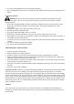
KNOWING YOUR BRUSH CUTTER Please use the illustration below to familiarize yourself with the location and function of the components that control of your brush cutter. Fig.1 1 2 3 4 5 6 7 8 Unpacking Blade Blade Shield Shaft Connector Cover D-Handle On/Off Switch Safety Lever Throttle Trigger 9 10 11 12 13 14 15 16 Purge Bulb Fuel Tank Lid Fuel Tank Air Cleaner Cover Choke Starter Handle Cut-off Knife Trimmer head Unpack the blower and all its parts, and compare against the list below.
ASSEMBLY INSTRUCTION The following section describes steps necessary to prepare the brush cutter for initial use. If after reading this section, you are unsure about how to perform any of the steps please call (800) 791-9458 Mon-Fri 9-5 EST for customer service. Failure to perform these steps properly can damage the brush cutter or shorten its lifespan. INSTALLING BRUSH CUTTER ATTCHEMENT CAUTION: When installing brush cutter attachment, place the unit on a flat surface for stability.
BLADE INSTALLATION WARNING: Wear protective gloves when handling or performing maintenance on the blade to avoid injury. The blade is sharp and can cut you even when it is not moving. WARNING: Do not attempt to use any blades, washers, nuts, or fastening hardware other than shown in the following illustrations. These parts must be provided by the manufacturer and installed as shown below. Failure to use proper parts can cause the blade to fly off and seriously hurt you or others. 1.
USING THE SHOULDER HARNESS 1. 2. 3. 4. 5. 6. WARNING: Proper shoulder strap and handlebar adjustments must be made with the engine completely stopped before using unit. Assemble and adjust the shoulder harness and belt (See fig.8). Adjust the shoulder-harness button,and move the hook to your waist, then adjust the belt (If there is a belt). Hang the latch tab on the harness hook. If the brush cutter doesn't balance,then adjust the harness hanger,and the handlebar,until the it balances.
WARNING: Fuel mixture at the rate other than 50:1 may cause damage to the engine,Ensure mixture ratio is correct. Do not mix gasoline and oil directly in the engine fuel tank. WARNING: The engine exhaust from this product contains chemicals known to cause cancer, birth defects, or other reproductive harm. Fig.
OPERATION WARNING: Be sure to read the fuel information in the safety rules before you begin. If you do not understand the safety rules, do not attempt to fuel your unit. Call customer support. CHECK POINTS BEFORE OPERATION Check for loose bolts, nuts and fittings. Check the air cleaner for dirt. Clean the air filter of all dirt, etc. before operation. Check to be sure that protector is securely in place. Check to be sure that fuel is not leaking. Check to be sure that blade is not cracked.
CUTTING WITH A NYLON HEAD Line head rotates in a counter CLOCKWISE direction.The CUT-OFF KNIFE will be on the right side of the debris shield (See fig.11). For nearly all cutting, it is good to tilt the line head so that contact is made on the part of the line circle where the line is moving away from you and the debris shield. This results in the debris being thrown away from you. Fig.11 Fig.12 WARNING: The proper debris shield must be in place on the unit when nylon cutting line is used.
Scalping and edging (See fig.14,15) WARNING: Do not use a steel blade for edging or scalping. Both of these are done with the line head tilted at a steep angle. Scalping is removing top growth.Edging is trimming the grass back where it has spread over a sidewalk or drive way. During both edging and scalping, hold the unit a steep angle and in a position where the debris, and any dislodging dirt and stones, will not come back towards you even if it ricochets off the hard surface.
Blade thrust is the reaction which may occur when the spinning blade contacts anything it cannot cut.This contact may cause the blade to stop for an instant ?and suddenly "thrust" the unit away from the object that was hit.This reaction can be violent enough to cause the operator to lose control of the unit.Blade thrust may occur without warning if the blade snags ,stalls or binds.
EXHAUST PORT AND SILENCER Depending on the type of fuel used,the type and amount of oil used,and/or your operating conditions,the exhaust port and silencer may become blocked with carbon deposits.Ifyou notice a power loss with your petrol powered tool. A qualified service technician will need to remove these deposits to restore performance. ADJUSTING CARBURETOR NOTE: Do not adjust carburetor unless necessary. If you have trouble with the carburetor, see your dealer.
TRANSPORT&STORAGE TRANSPORT, HANDLING WARNING: Please empty the fuel tank before transporting, to avoiding the engine leaked. For avoiding the cutting attachment damaged the brush cutter and people, please removed the cutting attachment ,and at the same time, resile the brush cutter as factory state , and then casting all parts into the package. Before transporting, all parts should be packed and validated safe. The engine should be turned off when the unit is moved between work areas.
TROUBLESHOOTING 1 .
2 .
EXPLODED VIEW AND PARTS LIST Engine exploded view 22
Engine parts list Item 1 Stock # GB70.1+GB93+GB97 Description Screw M5×16 Qty 4 Item Stock # Description Qty 35 CG305F-HS.1-3 Rubber 1 2 P23.10A Starter 1 36 CG305F-HS.1-1 Holder A 1 3 P23.9A Guide Cover assy 1 37 CG305F-HS.1-2 Holder B 1 4 1E36F.2 Oil seal 2 38 GB70.1+GB93+GB97 Screw M5×16 1 5 P23.11-2 Crank case R 1 39 GB70.1+GB93+GB97 Screw M5×25 2 6 GB/T119.1 Pin 4×h8×8 2 40 P23-7 7 GB/T276 41 P23.3 Insulator 1 8 P23.
Brush cutter &String trimmer exploded view Item Stock # Description Qty A PS4532-A Gear Case Ass’y 1 1 PS4532-A-001 Stop Ring 26 1 2 PS4532-A-002 Stop Ring 10 1 3 PS4532-A-003 Bearing 6000-2RS/P6 1 4 PS4532-A-004 Bearing 6000/P6 2 5 PS4532-A-005 Pinion 1 6 PS4532-A-006 Screw M5×20 1 7 PS4532-A-007 Screw M5×12 4 8 PS4532-A-008 Bolt 1 9 PS4532-A-009 Gear Case 1 10 PS4532-A-010 Safety Guard 1 11 PS4532-A-011 Gear 1 12 PS4532-A-012 Gear Shaft 1 13 PS4532
Item Item Stock # F PS4532-F 1 Description Stock # Description Qty D PS4532-D Fore-Pipe Comp. 1 1 PS4532-D-001 Hose Sleeve 1 2 PS4532-D-002 Rubber Cover 3 3 PS4532-D-003 Oil-bearing 3 4 PS4532-D-004 Drive Shaft 1 5 PS4532-D-005 Pipe 1 Item Stock # Description Qty E PS4532-E Rear-Pipe Comp.
Item Stock # Description Qty G PS4532-G Level Ass’y 1 1 PS4532-G-001 Clamp 1 2 PS4532-G-002 Screw M5×16 1 3 PS4532-G-003 Tine 1 4 PS4532-G-004 Spring 1 5 PS4532-G-005 Spring 1 6 PS4532-G-006 Spring 1 7 PS4532-G-007 Safety Lever 1 8 PS4532-G-008 Throttle Lever 1 9 PS4532-G-009 Cable Comp. 1 10 PS4532-G-010 Screw M5×25 2 11 PS4532-G-011 Nut M5 3 12 PS4532-G-012 Box, left 1 13 PS4532-G-013 Stop Switch 1 14 PS4532-G-014 Tube (12.
Item Stock # Description Qty I PS4532-I Guard Ass’y 1 1 PS4532-I-001 Bracket 1 2 PS4532-I-002 Screw M5×30 2 3 PS4532-I-003 Screw M5×12 1 4 PS4532-I-004 Screw ST4.2×16 1 5 PS4532-I-005 Safety Guard 1 6 PS4532-I-006 Screw M5×16 4 7 PS4532-I-007 Guard Ass’y 1 8 PS4532-I-008 Guard 1 9 PS4532-I-009 Screw ST4.
TWO (2) YEARS LIMITED WARRANTY PowerSmart is committed to building equipment that will provide years of dependable service. Our warranties are consistent with our commitment and dedication to quality. TWO (2) YEARS LIMITED WARRANTY OF POWER SMART PRODUCTS FOR HOME USE. PowerSmart (“Seller") warrants to the original purchaser only, that all PowerSmart consumer power tools will be free from defects in material or workmanship for a period of two (2) years from date of purchase.