PT20-EC PT20-ECRR PT25-EC PT25-ECRR Operators Manual Power Technology Southeast, Inc.
FORWARD You are now the proud owner of a Power Technology Generator powered by a Kubota engine. This engine is a product of Kubota’s quality engineering and manufacturing. The engine is made with fine materials and manufactured under the strictest quality control standards and will assure you long satisfactory service. To obtain the best use of your engine, please read this manual carefully.
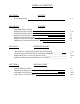
TABLE of CONTENTS SECTION 1: “SAFETY” 1-4 SAFE OPERATION SECTION 2: “ENGINE” PRE-OPERATION CHECK OPERATING THE ENGINE ENGINE SPECIFICATIONS ENGINE MAINTENANCE SERVICE SCHEDULE ENGINE OIL MAINTENANCE ENGINE COOLANT MAINTENANCE OPERATING HOURS AND SERVICE LOG SECTION 3: “GENERATOR END” “MAGNAPLUS” SERIES EXCITER TYPE GENERATOR ___________ _ GENERATOR EXPLODED VIEW and PARTS NUMBERS_________________ MARATHON SE350 VOLTAGE REGULATOR___________________________ WIRING SCHEMATICS and RESISTANCE CHARTS____
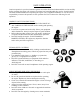
SECTION 1 “SAFETY” SAFE OPERATION 1-4 Observe Safety Instructions Wear Safety Clothing Check Before Operating the Engine Keep Area Around the Engine Clean Safe Handling of Fuel and Lubricants Exhaust Gases and Fire Prevention Escaping Fluids Cautions Against Burns and Battery Explosion Keep Hands and Body Away From Rotating Parts Anti-Freeze and Disposal of Fluids Conducting Safety Checks and Maintenance This symbol, the industry’s “Safety Alert Symbol”, is used throughout this manual and on labels attac
SAFE OPERATION Cautious operation is your best insurance against an accident. Read and understand this section carefully before operating the engine. All operators, no matter how knowledgeable they may be, should read this and other related manuals before operating the engine or any equipment attached to it. It is the owner’s responsibility to instruct all operators in safe operation. Be sure to observe the following for safe operation.
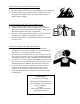
KEEP AREA AROUND THE ENGINE CLEAN • Be sure to stop the engine before cleaning. • Keep the engine clean and free of accumulated dirt, grease and trash. • DO NOT stop the engine without idling; Temperatures around the engine rises suddenly. Keep the engine idling for about 5 minutes before stopping. SAFE HANDLING OF FUEL AND LUBRICANTS • Always stop the engine before refueling or lubricating. • DO NOT smoke or allow flames or sparks in your working area. Fuel is extremely flammable and explosive.
ESCAPING FLUIDS • Relieve all pressure in the air, oil and cooling systems before any lines, fittings or related items are removed or disconnected. • Be alert for possible pressure release when disconnecting any device from a system that is pressurized. DO NOT check for pressure leaks with your hands. High-pressure oil or fuel can cause personal injury. • Escaping hydraulic fluid under pressure has sufficient force to penetrate skin causing serious personal injury.
ANTI-FREEZE AND DISPOSAL OF FLUIDS • Anti-freeze contains toxic chemicals. Wear rubber gloves when handling anti-freeze. In case of contact with skin, wash immediately to avoid personal injury. • DO NOT mix different types of Anti-freeze. The mixture can produce a chemical reaction resulting in the formation of harmful substances. Only use anti-freeze that is recommended and approved by Caterpillar. • Be mindful of the environment.
SECTION 2 “ENGINE” PRE-OPERATION CHECK 1 Engine Break-in Period Daily Check OPERATING THE ENGINE 2-12 Power Control Module Feature Summary Operating Behavior Automatic Generator Start (AGS) Safety Monitoring and Shutdown LED Sequences Troubleshooting Guides 12V DC Power Control Module Wiring Schematic ENGINE SPECIFICATIONS 13 Kubota Model V2203-M and V2003-M-T Service Parts ENGINE MAINTENANCE SERVICE SCHEDULE 14 ENGINE OIL MAINTENANCE 15 Checking Engine Oil Level Lubricating Oil Specifications
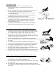
PRE-OPERATION CHECK ENGINE BREAK-IN PERIOD During the engine break-in period, observe the following recommendations: 1. Change the engine oil and oil filter cartridge after the first 50 hours of operation. (See “ENGINE OIL” in ENGINE MAINTENANCE SERVICE SCHEDULE). 2. In ambient temperature above 32°F (0°C) approximately 3-5 minutes without a load is sufficient for engine warm up. Allow additional warm up time when temperatures are below 32°F (0°C) before placing an operating load on the engine.
Power Controller Module (PCM) And Display (PCMD)
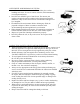
Feature Summary The PowerTech PCM controls all of the start and run processes and characteristics of any PowerTech generator. The features of the application are: Internal Ambient Temperature Sensor Provides an on-board temperature sensor. Oil Pressure Sensor / Switch Input Allows input from an external oil pressure sensor or switch. Will shut down the generator if sufficient pressure is not detected after a start-up period.
Operating Behavior Starting The generator starts in response to the “START” button being depressed for 1 second. The PCM goes into the Pre-Heat State, followed by the Cranking State, then finally, the Running State. The PCM attempts to start the generator a specific number of times (configuration parameter) before declaring a Fault. The shutdown inputs are checked before the start is attempted. If any of these inputs are active, the start process is aborted.
Automatic Generator Start (AGS) The Automatic Generator Start (AGS) allows the generator to start based upon the battery level. The trigger voltage is configurable via a configuration parameter. The entire feature can be enabled/disabled by a configuration parameter. The AGS feature is currently disabled, by default. Safety Monitoring And Shutdown The PCM monitors inputs for safety limitations which might damage the generator.
ENGINE TROUBLE SHOOTING ENGINE STARTS BUT WON’T RUN CODE 1 or 6 Failure To Start If “OK” Check Fuel System Check Fuel Filter/Supply Check Circuit To Actuator Bleed Air From System If “OK” Replace Actuator Check Fuel Pump / Circuit CODE 2 or 8 Engine High Water Temp.
ENGINE TROUBLE SHOOTING ENGINE STARTS BUT WON’T RUN CONTINUED CODE 3 or 8 Check Oil Level/Condition Low Oil Pressure 6 If “OK” Check Wiring From Sensor to Terminal 12 on PCM If “OK” Check Oil Pres.
ENGINE WILL NOT START ENGINE CRANKS No Exhaust Smoke ENGINE DOES NOT CRANK Battery Dead Smoke From Exhaust Check Fuel Solenoid Check Fuel Supply Check Glow Plugs 7 NO Power While Cranking YES Replace Solenoid Check Fuel Pump NO Air in Fuel System No Power From PCMD Check Spark Arrestor Muffler for Clogging ENGINE CRANKS SLOW Main Switch Oil Viscosity Too Heavy Check Terminals Turn Switch On Start Switch Low Battery Voltage Starter Motor
ENGINE RUNS ROUGH OR SLOW No Visible Exhaust Smoke Excessive Exhaust Smoke Insufficient Fuel to Engine BLUE SMOKE BLACK SMOKE GREY/WHITE SMOKE 8 Excessive Oil Level Check Fuel Level Replace Fuel Filter Air in Fuel System Check Fuel Pump Excessive Oil Consumption Dirty Air Filter Engine Cold Engine Overheated Incomplete Combustion Engine Overloaded Clogged Muffler Over Fueling Injector High Altitude Check Safety Shutdowns And Fuel Solenoid Glow Plug Circuit Not Operating Over Fueling Injec
ZERO or LOW VOLTAGE Check Main Breakers are “ON” OFF ON OK 9 Wiring To Panel Main Coil Output to Breakers BAD Defective Breaker / s BAD Check Brushes if Applicable Turn “ON” Breaker / s Replace Stator Check Ohm’s On Main Stator Leads OK Check Rotor Ohm’s
VOLTAGE TEST Zero or Low Voltage 10 Check Main Breaker / s On Generator Check Gen End High Voltage Overload Check Regulator Check AMP Draw From equipment Output Voltage OK
OVERLOAD CONDITION Check AMP Draw Check Load 11 Engine Problem See Engine Troubleshooting Check Stator Coil Resistance Replace Stator
12 VOLT DC WIRING SCHEMATIC POWER CONTROL MODULE and ELECTRONIC GOVERNOR for KUBOTA “M” SERIES ENGINES 12
ENGINE SPECIFICATIONS MODEL V2203-M V2003-M-T Air Induction Naturally Aspirated Turbo-Charged Continuous Output 32.5 HP @ 1800 rpm 36.6 HP @ 1800 rpm Cubic Capacity 134.07 in³ (2.19L) 121.99 in ³ (2.19L) Bore and Stroke 3.43 x 3.64 (87x92.4mm) 3.27 x 3.64 (83x92.4mm) Cylinder Arrangement 4 In-Line 4 In-Line Firing Order 1-3-4-2 1-3-4-2 Compression Ratio 23:1 22:1 Engine Oil Capacity 8.5 qts. (8.04L) API Class CF 8.5 qts. (8.
Engine Maintenance Service Schedule Maintenance Service Item Engine Oil Level Deterioration & Leakage *See Note Daily Every 150 Hours Every 500 Hours Every 1000 Hours Remarks X Engine Oil Change * X Or Once a Year Oil Filter Change * X Or Once a Year Coolant Level X Coolant Leakage X Coolant Change X Fuel Level X Fuel Leakage X As Necessary Fuel Filter Replacement X Air Filter Replacement X Damaged Worn Or Loose Belts ** Replace Fuel Hoses X Check Radiator Hoses & Clamps
ENGINE OIL MAINTENANCE CHECKING ENGINE OIL LEVEL KUBOTA V2203-M & V2003-M-T ENGINE REFILL CAPACITY Crankcase Oil Sump and Filter LUBRICATING OIL VISCOSITY RECOMMENDATIONS ( Y ) “ADD” mark. ( X ) “FULL” mark. 1. Maintain the engine oil level between “ADD” mark and “FULL” mark on oil level gauge. Do not fill crankcase above “FULL” mark. 2. Remove the oil filler cap and add oil, if necessary. Clean the oil filler cap. Install the oil filler cap.
ENGINE COOLANT MAINTENANCE COOLANT RECOMMENDATIONS COOLANT SERVICE LIFE For optimum performance, Power Technology recommends a 1:1 mixture of water / glycol. Coolant Type NOTE: Use a mixture that will provide protection against the lowest ambient temperature. NOTE: 100 percent pure glycol will freeze at a temperature of –23°C (-9°F). Most conventional heavy-duty coolant / antifreezes use Ethylene Glycol. Propylene Glycol may also be used in a 1:1 mixture with water.
OPERATING HOURS and SERVICE LOG THIS SERVICE LOG IS PROVIDED TO HELP YOU KEEP AN ACCUMULATIVE RECORD OF OPERATION HOURS ON YOUR GENERATOR SET AND THE DATES REQUIRED SERVICES WERE PERFORMED. ENTER TIME TO THE NEAREST HOUR. OPERATING HOURS DATE HRs.
SECTION 3 “GENERATOR END” “MAGNAPLUS” SERIES EXCITER TYPE GENERATOR ASSEMBLY NOTE: Pages 7 & 8 , 21 & 22 are Omitted.
GENERATOR 280–430 Frame Installation, Operation, and Maintenance Manual Marathon Electric Mfg. Corp. A REGAL-BELOIT COMPANY P.O. Box 8003 Wausau, WI 54402-8003 Phone: (715) 675 3359 Fax: (715) 675 8026 www.marathonelectric.
CONTENTS Safety Receiving and Storage Principles of Operation Installation Wiring Connections Operation Maintenance Testing Service Troubleshooting Specifications Parts List & Recommended Spare Parts When in doubt, ask. Questions are much easier to handle than mistakes caused by a misunderstanding of the information presented in this manual.
PRINCIPLES OF OPERATION FIGURE 1 -- MagnaPLUS® Circuit Diagram FIGURE 2 -- Typical MagnaPLUS® Layout Diagram 3
PRINCIPLE OF OPERATION generator KW in motor starting capability. For specific data contact Marathon Electric. MagnaPLUS® generators are brushless, self excited, externally voltage regulated, synchronous AC generator. The generator is made up of six major components: main stator (armature), main rotor (field), exciter stator (field), exciter rotor (armature), rectifier assembly, and voltage regulator.
GENERATOR MOUNTING Two Bearing Generators -- Direct Drive DISABLE AND LOCKOUT ANY ENGINE CRANKING DEVICES BEFORE ATTEMPTING TO INSTALL OR SERVICE THE GENERATOR. FOR ELECTRIC START SETS, DISCONNECT THE CRANKING BATTERY. FOR AIR START, DISCONNECT THE AIR SUPPLY. FOR MOTOR GENERATOR SETS, OPEN THE POWER SUPPLY TO THE DRIVE MOTOR. FAILURE TO COMPLY WITH THESE SAFETY PROCEDURES COULD RESULT IN SEVERE PERSONAL INJURY OR EQUIPMENT DAMAGE. Two bearing generators are provided with a keyed shaft extension.
The generator conduit box construction allows cable entry from multiple sides. A hole saw or other appropriate tool may be used to provide for conduit entrance. Protect the interior of the generator from shavings when drilling or sawing. An approved connector must be used in conjunction with the conduit. To minimize the transmission of vibration, it is essential that flexible conduit be used for all electrical entrance to the generator conduit box.
DEDICATED SINGLE PHASE CONNECTION HIGH VOLTAGE - SERIES CONNECTED VOLTAGE (DEDICATED) Hz L-L L-N 60 240 120 220 110 50 220 110 200 100 SINGLE PHASE CONNECTION - SINGLE VOLTAGE PARALLEL VOLTAGE 60 HZ 50 HZ L-L 120 110 Note: For 120 volt only service. Use an AVC63-4A or a VR63-4C voltage regulator to replace the standard SE350 regulator.
OPERATION START-UP The following procedure should be followed when starting the generator set for the first time. PRE-START INSPECTION Before starting the generator for the first time, the following inspection checks are recommended: 1. The generator output must be disconnected from the load. Be sure that the main circuit breaker or fused disconnect is in the open position. 1. A visual inspection should be made for any loose parts, bad connections, or foreign materials. 2. 2.
rather one that should be conducted by an authorized service center equipped with the appropriate apparatus and solvents necessary to properly clean and dry the generator. recommended practice to record the no load excitation (DC voltage to the exciter stator), generator terminal voltage, and driver speed as a benchmark for future troubleshooting. 8. Close the main circuit breaker to the load. 9. Monitor the generator output current to verify that it is at or below nameplate value.
that the generator’s air gaps (main rotor and exciter) are free from obstructions. If possible, rotate the generator manually to ensure free rotation. Never “bar over” the engine generator set using the generator fan. Forced Air Another method to dry the generator is to run the set with no excitation (see startup procedure item #2). The natural flow of ambient air through the generator will tend to dry the windings.
When the positive test probe is connected to the diode's anode and the negative test probe is connected to the diode's cathode (forward biased), the diode will switch on and conduct electricity (Figure 4). This is observed by a low resistance reading when using an ohm meter or the lighting of the bulb when using a battery light continuity tester. Reversing the test leads (reverse biased) will result in the diode switching off and no electricity will be conducted.
Reassembly note: Before the bearing bracket is seated against the frame, a threaded rod may be used to help align the inner bearing cap with the bearing bracket. Failure to remove the exciter field leads from the automatic voltage regulator during flashing procedures may destroy the regulator. BEARING REPLACEMENT 2. 3. Connect the F+ and F- leads to the battery’s corresponding positive and negative terminals.
430 FRAME 280 / 360 FRAME A - Exciter Rotor Lead, B - Main Rotor Lead, C - Red (+) Suppressor Lead, D - Black (-) Suppressor Lead FIGURE 5: ROTATING RECTIFIER ASSEMBLY RETURNED GOODS TROUBLESHOOTING Contact Marathon Electric Manufacturing Corporation for authorization before returning any product. We can not be responsible for any items returned without authorization. This section is intended to suggest a systematic approach to locating and correcting generator malfunctions.
WARNING HIGH VOLTAGES MAY BE PRESENT AT THE GENERATOR’S TERMINALS WHEN THE UNIT IS RUNNING. SOME ACCESSORY EQUIPMENT SUCH AS SPACE HEATERS MAY BE ENERGIZED FROM AN OUTSIDE POWER SOURCE WHEN THE UNIT IS AT REST. TOOLS, EQUIPMENT, CLOTHING AND YOUR BODY MUST BE KEPT CLEAR OF ROTATING PARTS AND ELECTRICAL CONNECTIONS. SPECIAL PRECAUTIONS MUST BE TAKEN DURING TROUBLESHOOTING SINCE PROTECTIVE COVERS AND SAFETY DEVICES MAY BE REMOVED OR DISABLED TO GAIN ACCESS AND PERFORM TESTS. BE CAREFUL.
GENERATOR PRODUCES LOW VOLTAGE WHEN LOAD APPLIED CAUSE CHECK AND REMEDY Excessive load Reduce load. The load on each leg should be evenly balanced, and rated current should not be exceeded on any leg. Large motor starting or low load power factor Motor starting currents are too large for the generator. When starting multiple motors, sequence the motors and start the largest motors first. Reduce lagging power factor load. Driver speed droop or belt slip Check driver.
GENERATOR BUILDS VOLTAGE FROM STARTUP, THEN GOES TO LOW (RESIDUAL) VOLTAGE CAUSE CHECK AND REMEDY Regulator protective circuit operating Check indicators on regulator. Correct problems and adjust regulator as is required. Refer to regulator manual. GENERATOR IS OVERHEATING CAUSE CHECK AND REMEDY Generator is overloaded Reduce load. Check with ammeter and compare with nameplate rating. Clogged ventilating screens Clean air passages.
SPECIFICATIONS EXCITER RESISTANCE STATOR ROTOR 18.0 .120 23.5 .120 23.0 .135 18.5 .120 18.0 .
PARTS LIST – SINGLE BEARING Typical Generator Cross Section 9 8 10 11 12 13 14 15 16 7 6 17 5 18 4 3 2 1 20 Reference Number 1 2 3 4 5 6 7 8 9 10 Note: Part Name Reference Number End Bracket (under end cover 360 & 430 frames) Bearing O-ring (280 and 360 frame only) Rectifier Assembly Air Intake Cover Exciter Rotor Exciter Stator Link Board (terminal block) Conduit Box Generator Frame 11 12 13 14 15 16 17 18 19 20 19 Part Name Main Stator Main Rotor Rotor Integral Keyway Fan Mounting Adapt
21 DESCRIPTION 1. END COVER 2. ROTOR BEARING 3. EXCITER ROTOR 4. EXCITER STATOR 5.
MARATHON SE350 VOLTAGE REGULATOR The SE350 electronic voltage regulator is designed to control the output of a brush less AC generator by regulating the current into the exciter field. Features include frequency compensation, automatic voltage build-up and EMI suppression. The SE350 attaches to the generator with spade type wire terminals for a secure connection. The SE350 has three adjustable potentiometers for finetuning the output voltage, stability and under frequency.
MARATHON SE350 VOLTAGE REGULATOR EXCITER POWER CIRCUIT: Connect the regulator wire F+ to the generator F+ or F1 field terminal. Connect the regulator wire F- to the generator F- or F2 field terminal SENSING / POWER INPUT CIRCUIT: Input power and sensing is achieved through terminals 3 and 4. The voltage input requirement of the SE350 is 190 to 240V AC. A 4 Amp 250V – 5x20 mm fuse is supplied with the regulator.
MARATHON SE350 VOLTAGE REGULATOR START-UP PROCEDURE: Ensure the voltage regulator is correctly connected to the generator. Refer to the specific connection diagram supplied with the generator. Set the regulator voltage adjust to full counter-clockwise (minimum voltage level). Set the stability control full clockwise (maximum stability level). Connect the positive lead of a 100V DC voltmeter to F1 and the negative lead of the voltmeter to F2 or use an appropriate AC voltmeter on the generator output leads.
25 Main Stator Main Rotor Exciter Stator Exciter Rotor Aux. Winding RESISTANCE CHART Marks Less Than 1.0 T1-T2 T3Ohm / Phase T4 2.10 N/A 23.0 – 28.0 F+ – C 0.655 – 0.720 N/A 1.0 – 1.
SECTION 4 “INSTALLATION” SAFETY PRECAUTIONS 1-2 Hot Piping Dangerous Fuels Explosive Battery Gases Electrocution Moving Parts High Voltage Explosion Hot Coolant Lethal Exhaust Gas Excessive Noise Electrical Shock Backfire Flash Fire Fire Hazard Marine Application Unit Starts Without Notice Loose Components GENERATOR INSTALLATION in RECREATIONAL VEHICLES 3-6 Introduction Marine Application General Information Specification Charts Fuel Consumption in Gallons per Hour Installation Factors Generator Compar
SAFTEY PRECAUTIONS A generator set can be potentially dangerous if not properly maintained and operated. The best Safe Guard against a dangerous situation is education, good judgment and common sense. For safe trouble free operation of your generator set some general precautions are listed below. Be sure to read, understand and follow these precautions. Please call Power Technology Southeast, Inc. with any concerns you may have with your generator set.
7) EXPLOSION: Never connect the negative (-) battery cable to the positive (+) connection terminal of the starter solenoid, or test the battery by shorting terminals together. This could ignite fuel vapors or cause the battery to explode. To disconnect the battery remove the negative battery cable first and reconnect it last. Do not modify the fuel tank or propulsion engine fuel system. Your vehicle must be equipped with a fuel pick-up arrangement as described in the Fuel System section of this manual.
GENERATOR INSTALLATION In RECREATIONAL VEHICLES INTRODUCTION Use this section as a guide when installing a generator set in a recreational vehicle, and then refer to the appropriate operation section for specific instructions. When installing a EC generator set the installation must comply with the current Safety Standards of ANSI / RVIA EGS-1-2003, ANSI A 119.2 / NFPA 501C and applicable articles of ANSI / NFPA 70 of the National Electrical Code.
SPECIFICATION CHARTS FUEL CONNECTION FUEL RECOMMENDATION BATTERY VOLTAGE BATTERY CRANKING AMPS BATTERY COLD CRANKING AMPS BATTERY GROUND CHARGING AMPS. ¼” NPT DIESEL FUEL No.1-D or No.2-D ASTM / D975 12 VOLTS DC 420 590 MINIMUM NEGATIVE 40 FUEL CONSUMPTION IN GALLONS PER HOUR LOAD PERCENTAGE 25% 50% 75% 100% 20KW .39 GPH .79 GPH 1.18 GPH 1.57 GPH 25KW .45 GPH .90 GPH 1.35 GPH 1.
GENERATOR COMPARTMENT SIZE In planning the size of the generator compartment allow for the minimum clearance of one (1) inch necessary to adequately cool the generator set. The thickness of insulation and sound deadening material used to line the compartment must be taken into consideration when planning this clearance. To maintain minimum clearance it may be necessary to enlarge the compartment.
AIR REQUIREMENTS CONT’D ENGINE SPEED IN RPM OUTPUT IN HORSEPOWER WATER FLOW – GAL. / MIN. ENGINE INLET WATER TEMP. THERMOSTAT – RATING THERMOSTAT FULL OPEN ENGINE OUTLET WATER TEMP.MAX. HIGH TEMP. SHUTDOWN SWITCH HEAT REJECTION – BTU / MIN. HEAT REJECTION – BTU / HR. REMOTE RADIATOR AIR FLOW – CU. FT. / MIN. ENGINE OIL TEMP. MAX. COMBUSTION AIR TEMP. * 20 / 25 KW 1800 32.5 / 36.6 8.
SYSTEMS CONNECTION REMOTE RADIATOR COOLING SYSTEM Use the following data in designing and installing the generator set cooling system. To insure a safe effective installation, be sure the cooling system selected follows these parameters. Power Technology offers radiator assemblies, which meet these requirements and will adequately cool the generator. Select the radiator assembly best suited for the generator installation.
SYSTEMS CONNECTION FUEL SYSTEM The diesel fuel system for the generator set must be designed to operate independently from the vehicles main engine if both engines are to be operated at the same time. The best way to do this is to have separate fuel tanks, but this is usually impractical because of space restrictions. In most installations both engines operate from a common fuel tank with separate pick-up tubes for each engine, not a Tee fitting arrangement.
EXHAUST SYSTEM IMPORTANT SAFETY TIPS: When exhaust system components are not furnished by Power Technology as part of the Genset, the installer is responsible for meeting the following requirements. 1) Only use exhaust system components, which do not restrict exhaust flow. A restricted exhaust system will create excessive backpressure and may cause poor engine performance and possible engine damage. The maximum allowable backpressure for the engines listed in this manual is 1.57in Hg, (40mmHg).
10
ELECTRICAL CONNECTIONS ELECTRICAL WIRING All wiring must be applicable with local electrical codes. A qualified licensed electrician must perform all electrical wiring connections. Ground Fault (GFCI) breakers must be installed to protect all vehicle branch circuits. All switches and controls must be securely mounted to prevent damage and accidental opening or closing from vibration, road shock and vehicle motion.
MOTOR LOADS When figuring generator set capacity requirements for installation involving motor loads, do not overlook the high current demanded by the motor during start-up. The “In-Rush” of starting current may be 2 to 5 times higher than that required when the motor reaches normal operating speed. Reserve capacity must be allowed for in rush demands plus other loads, which could be on the line as the motor starts.
APPLIANCE LOADS Generator sets in recreational vehicles are often used to supply AC voltage for appliances. With the exception of a resistance-type load such as a water heater, requirements for appliances are usually low. However, such loads must not be overlooked when calculating the total wattage requirements. To avoid an overload situation, reserve capacity should also be calculated for unanticipated appliance loads.