02/15/01 ® Powerware 5115 User’s Guide 500–1400 VA www.powerware.
Class B EMC Statements FCC Part 15 NOTE This equipment has been tested and found to comply with the limits for a Class B digital device, pursuant to part 15 of the FCC Rules. These limits are designed to provide reasonable protection against harmful interference in a residential installation. This equipment generates, uses and can radiate radio frequency energy and, if not installed and used in accordance with the instructions, may cause harmful interference to radio communications.
® Powerware 5115 User’s Guide 500–1400 VA www.powerware.
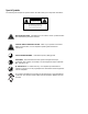
Special Symbols The following are examples of symbols used on the UPS to alert you to important information: CA U T I O N Risk of Electric Shock Do Not Open Cover CAUTION To reduce the risk of electric shock, Do not remove cover (or back) No user-serviceable parts inside Refer servicing to the factory RISK OF ELECTRIC SHOCK - Indicates that a risk of electric shock is present and the associated warning should be observed.
TABLE OF CONTENTS 1 Powerware 5115 – One of the Best! . . . . . . . . . . . . . . . . . . . . . . . . . . . . . . . . . . 1 2 Installation . . . . . . . . . . . . . . . . . . . . . . . . . . . . . . . . . . . . . . . . . . . . . . . . . . . . . 3 Inspecting the Equipment . . . . . . . . . . . . . . . . . . . . . . . . . . . . . . . . . . . . . . . . . . . . . . . . . . . . . . . Safety Precautions . . . . . . . . . . . . . . . . . . . . . . . . . . . . . . . . . . . . . . . . . . . . . . . . . . . . . . . .
Table of Contents ii Powerware® 5115 User’s Guide S www.powerware.
CHAPTER 1 POWERWARE 5115 – ONE OF THE BEST! The PowerwareR 5115 uninterruptible power system (UPS) protects your sensitive electronic equipment from basic power problems such as power failures, power sags, power surges, brownouts, and line noise. Power outages can occur when you least expect it and power quality can be erratic. These power problems have the potential to corrupt critical data, destroy unsaved work sessions, and damage hardware — causing hours of lost productivity and expensive repairs.
Powerware 5115 – ONE OF THE BEST! Because an integral part of power protection is power management software, the Powerware 5115 comes fully equipped with a communication port, serial cable, and a CD containing both LanSafe III for networked systems and FailSafe III for standalone systems.
CHAPTER 2 INSTALLATION This section explains: S Equipment inspection S Safety precautions S UPS installation S UPS rear panels Inspecting the Equipment If any equipment has been damaged during shipment, keep the shipping cartons and packing materials for the carrier or place of purchase and file a claim for shipping damage. If you discover damage after acceptance, file a claim for concealed damage.
Installation WARNING S This UPS contains its own energy source (batteries). The output receptacles may carry live voltage even when the UPS is not connected to an AC supply. S Do not remove or unplug the input cord when the UPS is turned on. This removes the safety ground from the UPS and the equipment connected to the UPS. S To reduce the risk of fire or electric shock, install this UPS in a temperature and humidity controlled, indoor environment, free of conductive contaminants.
Installation 1 NOTE Connect communication cable from computer to UPS (optional) This is a typical setup; your setup may vary. 5 Press the ON button (on the front panel) 2 & 3 Connect UPS to power 4 Connect equipment to UPS Figure 2. Typical UPS Installation (120V Model Shown) 3. Plug the UPS power cord into a power outlet. 4. Plug the equipment to be protected into the UPS output receptacles.
Installation UPS Rear Panels This section shows the rear panels of the Powerware 5115 models. Site Wiring Fault Indicator DIP Switches Network Transient Protector Communication Port Four 5-15 Receptacles Input Overcurrent Protector 6-ft Power Cord with 5-15 Plug Figure 3. 500 VA, 120V Rear Panel Site Wiring Fault Indicator DIP Switches Network Transient Protector Communication Port Fan Four 5-15 Receptacles Input Overcurrent Protector 6-ft Power Cord with 5-15 Plug Figure 4.
Installation Site Wiring Fault Indicator DIP Switches Network Transient Protector Communication Port Two 5-15 Receptacles Fan Four 5-15 Receptacles Input Overcurrent Protector 6-ft Power Cord with 5-15 Plug Figure 5. 1000 VA, 120V Rear Panel Site Wiring Fault Indicator DIP Switches Network Transient Protector Communication Port Fan Six 5-15 Receptacles Input Overcurrent Protector 6-ft Power Cord with 5-15 Plug Figure 6. 1400 VA, 120V Rear Panel Powerware® 5115 User’s Guide S www.powerware.
Installation Network Transient Protector Communication Port DIP Switches Four 10A, IEC-320 Receptacles Input Overcurrent Protector 10A, IEC-320 Input Connector Figure 7. 500 VA, 230V Rear Panel Communication Port DIP Switches Network Transient Protector Fan Four 10A, IEC-320 Receptacles Input Overcurrent Protector 10A, IEC-320 Input Connector Figure 8. 750 VA, 230V Rear Panel 8 Powerware® 5115 User’s Guide S www.powerware.
Installation Communication Port DIP Switches Network Transient Protector Fan Four 10A, IEC-320 Receptacles Two 10A, IEC-320 Receptacles Input Overcurrent Protector 10A, IEC-320 Input Connector Figure 9. 1000 VA, 230V Rear Panel Communication Port DIP Switches Network Transient Protector Fan Six 10A, IEC-320 Receptacles 10A, IEC-320 Input Connector Input Overcurrent Protector Figure 10. 1400 VA, 230V Rear Panel Powerware® 5115 User’s Guide S www.powerware.
Installation 10 Powerware® 5115 User’s Guide S www.powerware.
CHAPTER 3 OPERATION This section describes: S Turning the UPS on and off S Starting the UPS on battery S Standby mode S The UPS front panel and LEDs S Initiating the self-test Turning the UPS On To turn on the UPS, press the button on the front panel (shown in Figure 11). After the UPS is turned on, it conducts a self-test and enters indicator illuminates indicating that power is Normal mode. The available from the UPS output receptacles.
Operation Standby Mode When the UPS is turned off and remains plugged into a power outlet, the UPS is in Standby mode. The battery recharges when necessary and indicator is off, indicating that power is not available from the the UPS output receptacles. µ UPS Front Panel The UPS front panel indicates the UPS status and also identifies potential power problems. Figure 11 shows the UPS front panel indicators and controls.
CHAPTER 4 ADDITIONAL UPS FEATURES This section describes: S Changing the voltage configuration S Using the communication port S The Network Transient Protector Voltage Configuration The DIP switches on the rear panel of each unit (see Figure 12) are used to configure the output voltage and input voltage range. 1. The UPS must be completely shutdown. Turn the UPS off by pressing the and then unplug the UPS. button on the front panel 2.
Additional UPS Features Table 1.
Additional UPS Features Table 2.
Additional UPS Features 16 Powerware® 5115 User’s Guide S www.powerware.
CHAPTER 5 UPS MAINTENANCE This section explains how to: S Care for the UPS and batteries S Replace the batteries S Test new batteries S Recycle used batteries UPS and Battery Care For the best preventive maintenance, keep the area around the UPS clean and dust-free. If the atmosphere is very dusty, clean the outside of the system with a vacuum cleaner. For full battery life, keep the UPS at an ambient temperature of 25°C (77°F).
UPS Maintenance Replacing Batteries The hot-swappable battery feature allows you to replace the UPS batteries easily without turning the UPS off or disconnecting the load. If you prefer to remove input power to change the battery, press the button and then unplug the UPS. Consider all warnings, cautions, and notes before replacing batteries. WARNING S Batteries can present a risk of electrical shock or burn from high short circuit current.
UPS Maintenance Use the following steps to replace the batteries: 1. Pull the top left corner forward and remove the front panel. 2. Slide up and remove the metal battery cover. 3. 500 VA units. Disconnect the red battery cable and then disconnect the black battery cable. Pull the battery out onto a flat, stable surface. Powerware® 5115 User’s Guide S www.powerware.
UPS Maintenance 4. 750–1400 VA units. Disconnect the red battery cable and then pull the battery out onto a flat, stable surface. Disconnect the black battery cable to the UPS as shown. 750/1000 VA 1400 VA 20 Powerware® 5115 User’s Guide S www.powerware.
UPS Maintenance 5. Replace the battery. See “Recycling the Used Battery” for proper disposal. 6. Connect the black battery cable to the new battery and then connect the red battery cable. 7. Reinstall the battery. 8. Reinstall the metal battery cover and front panel. Testing New Batteries NOTE It is recommended that the batteries charge for 6 to 24 hours before testing. Press and hold the button for three seconds to initiate a self-test.
UPS Maintenance 22 Powerware® 5115 User’s Guide S www.powerware.
CHAPTER 6 SPECIFICATIONS This section provides the following specifications for the Powerware 5115 models: S Weights and dimensions S Electrical input and output S Environmental and safety S Battery Table 3. Model List and Mechanical UPS Models UPS Dimensions (WxHxD) 120V Models 230V Models PW5115 500 PW5115 750 PW5115 1000 PW5115 1400 PW5115 500i PW5115 750i PW5115 1000i PW5115 1400i 500 VA: 15.0 x 19.3 x 27.0 cm (5.9² x 7.6² x 10.6²) 750–1000 VA: 15.0 x 19.3 x 33.5 cm (5.9² x 7.6² x 13.
Specifications Table 5. Electrical Output 120V Models 230V Models Power Levels (rated at nominal inputs) 500 VA, 320W 750 VA, 500W 1000 VA, 670W 1400 VA, 950W Power Factor 500 VA, 0.64 750–1400 VA, 0.
Specifications Table 7. Battery Configuration 500 VA: (1) 12V, 9 Ah internal battery 750 VA: (2) 12V, 7.
Specifications 26 Powerware® 5115 User’s Guide S www.powerware.
CHAPTER 7 TROUBLESHOOTING This section explains: S Site wiring fault on 120V models S UPS alarms and conditions S How to silence an alarm S Service and support Site Wiring Fault (120V Models Only) The Site Wiring Fault indicator on the UPS rear panel illuminates if the ground wire connection does not exist or the line and neutral wires are reversed in the line receptacle. This indicator stays on until the condition is resolved. Have a qualified electrician correct the wiring fault.
Troubleshooting Indicator Legend Unlit Lit Flashing Table 9. Troubleshooting µ Alarm or Condition Possible Cause Action The indicator is not on; the UPS does not start. The power cord is not connected. Check the power cord connections. The wall outlet is faulty. Have a qualified electrician test and repair the outlet. The UPS operates in Battery mode only, even though normal utility power is present. The input overcurrent protector is open. Save your work and turn off your equipment.
Troubleshooting Alarm or Condition Possible Cause Action 1 beep every 2 seconds. The UPS is running on battery power because the input voltage is too high or too low. Correct the input voltage, if possible. The UPS continues to operate on battery until the condition is corrected or the battery is completely discharged. If the condition persists, the input voltage in your area may differ from the UPS nominal.
Troubleshooting Alarm or Condition 30 Possible Cause Action 3 beeps every 10 seconds. Failed attempt to start the UPS on battery. Plug the UPS into a power outlet for 24 hours to charge the battery. After charging the battery, press and hold the button for 3 seconds; then check the indicator. If the indicator still flashes, see “UPS Maintenance” on page 17 to replace the battery. Continuous beep. The output wave is abnormal while the UPS is on battery. Shutdown is imminent.
Troubleshooting Service and Support If you have any questions or problems with the UPS, call your Local Distributor or the Help Desk at one of the following telephone numbers and ask for a UPS technical representative.
Troubleshooting 32 Powerware® 5115 User’s Guide S www.powerware.