02/20/2001 ® Powerware 9150 User’s Guide 8 kVA - 12.5 kVA www.powerware.
FCC Statement The Powerware9 9150 UPS configurations vary. Some configurations may or may not be classified by the Federal Communications Commission (FCC) as a Class A device. If your Powerware 9150 unit is classified by these standards, the corresponding information applies: Class A NOTE This equipment has been tested and found to comply with the limits for a Class A digital device, pursuant to Part 15 of the FCC Rules.
Table of Contents TABLE OF CONTENTS 1 Introduction . . . . . . . . . . . . . . . . . . . . . . . . . . . . . . . . . . . . . . . . . . . . . . . . . . . . 1 UPS Model and Battery Configurations . . . . . . . . . . . . . . . . . . . . . . . . . . . . . . . . . . . . . . . . . . . . . . Load Requirements . . . . . . . . . . . . . . . . . . . . . . . . . . . . . . . . . . . . . . . . . . . . . . . . . . . . . . . . . Battery Times . . . . . . . . . . . . . . . . . . . . . . . . . . . . . . . . . . . . . . . .
Table of Contents 4 Operation . . . . . . . . . . . . . . . . . . . . . . . . . . . . . . . . . . . . . . . . . . . . . . . . . . . . . . 39 Control Panel Functions . . . . . . . . . . . . . . . . . . . . . . . . . . . . . . . . . . . . . . . . . . . . . . . . . . . . . . . . . NEED NEW LOGO . . . . . . . . . . . . . . . . . . . . . . . . . . . . . . . . . . . . . . . . . . . . . . . . . . . . . . . . . . . . . Operating Modes . . . . . . . . . . . . . . . . . . . . . . . . . . . . . . . . . . . . . . . .
CHAPTER 1 INTRODUCTION The Powerware9 9150 is a double-conversion, online uninterruptible power supply (UPS) for protecting computer systems and other intelligent devices. The UPS provides a steady, well-regulated power supply for your computing and communications equipment, while protecting it from the frequent irregularities that are inherent in commercially available power.
Introduction UPS Model and Battery Configurations There are two important considerations when selecting the UPS model and battery configuration to properly safeguard your equipment: : The UPS output power rating (VA) should be specified according to the total power demand of the equipment to be protected. Some margin should be allowed for potential expansion of the protected system, and for possible inaccuracy in calculating or measuring the actual power requirement.
Introduction If the total load requirements of the equipment exceeds the capacity of the UPS, you must either reduce the number of pieces of equipment, or use a UPS with a larger load capacity. NOTE Line-to-neutral loads (100V - 127V) should be balanced between L1/A and L2/B. When deciding on which pieces of equipment to remove from the UPS, select equipment that has a lower priority for power protection.
Introduction If a power failure outlasts the backup time, the UPS shuts down in order to prevent a total discharge of the battery. When utility is restored, the UPS starts automatically, providing power to the critical load and charging the battery bank. 4 Powerware® 9150 User’s Guide : www.powerware.
CHAPTER 2 SAFETY WARNINGS The only user operations permitted are: : Starting up and shutting down the UPS : Operating the user interface : Connecting data interface cables : Monitoring the UPS with power management software WARNING Only qualified service personnel (such as a licensed electrician) should perform the UPS installation and initial startup. Risk of electrical shock. These operations must be performed according to the instructions in this manual.
Safety Warnings DANGER This UPS contains LETHAL VOLTAGES. All repairs and service should be performed by AUTHORIZED SERVICE PERSONNEL ONLY. There are NO USER SERVICEABLE PARTS inside the UPS. CAUTION 6 : Output overcurrent protection and disconnect switch must be provided by others (see table on page 21).
Safety Warnings Sikkerhedsanvisninger FARE Denne UPS (ubrudt strømforsyning) indeholder LIVSFARLIG SPÆNDING. Al reparation og service bør KUN foretages af AUTORISERET SERVICEPERSONALE. Der er INGEN DELE i UPS’en, hvorpå en BRUGER BØR FORETAGE SERVICE. ADVARSEL : Batterier kan give risiko til elektrisk stød eller forbrænding fra stærk kortslutningsstrøm. Observer korrekte forholdsregler. : Korrekt afkastning af batterier kræves. Henvend Dem til deres lokale love m.h.t. affaldsreguleringer.
Safety Warnings Belangrijke Veiligheidsinstructies GEVAAR Deze UPS bevat LEVENSGEVAARLIJKE ELEKTRISCHE SPANNING. Alle reparaties en onderhoud dienen UITSLUITEND DOOR ERKEND SERVICEPERSONEEL te worden uitgevoerd. Er bevinden zich GEEN ONDERDELEN in de UPS die DOOR DE GEBRUIKER kunnen worden GEREPAREERD. OPGELET 8 : Batterijen kunnen gevaar voor elektrische schok of brandwonden veroorzaken als gevolg van hoge kortsluitstroom. Volg de desbetreffende aanwijzingen op.
Safety Warnings Tärkeitä turvaohjeita VAARA Tämä UPS sisältää HENGENVAARALLISIA JÄNNITTEITÄ. Kaikki korjaukset ja huollot on jätettävä VAIN VALTUUTETUN HUOLTOHENKILÖSTÖN TOIMEKSI. Tämä UPS ei sisällä MITÄÄN KÄYTTÄJÄN HUOLLETTAVIA OSIA. VARO : Akusto saattaa aiheuttaa sähköiskun vaaran tai syttyä tuleen mikäli akusto kytketään oikosulkuun. Noudata asianmukaisia ohjeita. : Akusto täytyy hävittää säädösten mukaisella tavalla. Noudata paikallisia määräyksiä.
Safety Warnings Consignes de Sécurité Consignes Importantes De Sécurité - Conserver Ces Instructions Cette Notice Contient Des Consignes Importantes De Sécurité ATTENTION! Cet UPS contient des tensions mortelles. Toute opération d’entretien et de réparation doit être effectuée UNIQUEMENT PAR UN PERSONNEL QUALIFIÉ AGRÉE. L’UPS n’a AUCUNE PIÈCE RÉPARABLE PAR L’UTILISATEUR. DANGER! 10 : Une batterie peut présenter un risque de choc électrique ou de brûlure par un transfert d’énergie ou un court-circuit.
Safety Warnings Wichtige Sicherheitsanweisungen WARNUNG Lebensgefahr! Diese USV enthält TÖDLICHE SPANNUNGEN! Alle Reparatur- und Wartungsarbeiten sollten NUR VON AUTORISIERTEM WARTUNGSPERSONAL durchgeführt werden. In dieser USV befinden sich KEINE VOM BENUTZER ZU WARTENDEN TEILE. VORSICHT! : Batterien können aufgrund von Kurzschlußhochstrom Elektroschocks oder Verbrennungen verursachen. Entsprechende Anleitungen befolgen. : Die Batterien müssen ordnungsgemäß weggeworfen werden.
Safety Warnings Importanti istruzioni di sicurezza PERICOLO La TENSIONE contenuta in questo gruppo statico di continuità è LETALE. Tutte le operazioni di riparazione e di manutenzione devono essere effettuate ESCLUSIVAMENTE DA PERSONALE TECNICO AUTORIZZATO. All’interno del gruppo statico di continuità NON vi sono PARTI RIPARABILI DALL’UTENTE. ATTENZIONE 12 : Le batterie possono presentare rischio di scossa elettrica o di ustioni provocate da alta corrente dovuta a corto circuito.
Safety Warnings Viktig Sikkerhetsinformasion FARLIG Denne UPS’en inneholder LIVSFARLIGE SPENNINGER. All reparasjon og service må kun utføres av AUTORISERT SERVICEPERSONALE. BRUKERE KAN IKKE UTFØRE SERVICE PÅ NOEN AV DELENE i UPS’en. FORSIKTIG : Batterier kan forårsake elektriske støt eller forbrenning på grunn av høy kortslutningsstrøm. Følg instruksene. : Batterier må fjernes på korrekt måte. Se lokale forskrifter vedrørende krav om fjerning av batterier.
Safety Warnings Regulamentos de Segurança CUIDADO O UPS contém VOLTAGEM MORTAL. Todos os reparos e assistência técnica devem ser executados SOMENTE POR PESSOAL DA ASSISTÊNCIA TÉCNICA AUTORIZADO. Não há nenhuma PEÇA QUE POSSA SER REPARADA PELO USUÁRIO dentro do UPS. PERIGO 14 : As baterias podem apresentar o risco de choque elétrico, ou queimaduras provenientes de alta corrente de curto-circuito. Observe as instruções adequadas. : Siga os devidos regulamentos ao desfazer-se das baterias.
Safety Warnings Requisitos de seguridad PELIGRO Este UPS (suministro de alimentación permanente) contiene VOLTAJES LETALES. Todas las reparaciones y el servicio técnico deberán ser realizados por PERSONAL DE SERVICIO TECNICO AUTORIZADO SOLAMENTE. Este UPS NO CONTIENE PARTES QUE PUEDAN SER REPARADAS POR EL USUARIO. PRECAUCIÓN : Las baterías pueden presentar un riesgo de descargas eléctricas o de quemaduras debido a la alta corriente de cortocircuito. Preste atención a las instrucciones correspondientes.
Safety Warnings Viktig säkerhetsinformation FARA Denna UPS-enhet innehåller LIVSFARLIG SPÄNNING. ENDAST AUKTORISERAD SERVICEPERSONAL får utföra reparationer eller service. Det finns inga delar som ANVÄNDAREN KAN UTFÖRA SERVICE PÅ inuti UPS-enheten. VIKTIGT 16 : Batterierna kan ge elektriska stötar eller brännskador från hög kortslutningsström. Följ tillämpliga anvisningar. : Batterierna måste kasseras enligt anvisningarna i lokal lagstiftning. : Denna UPS-enhet har en egen energikälla (batterier).
CHAPTER 3 INSTALLATION The following section describes UPS storage requirements, UPS setup, and the installation and startup of the UPS. The instructions are intended for the chief operator/system supervisor, electrical consultants, and installation electricians. Local regulations and electrical code must be followed in the UPS installation.
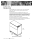
Installation UPS Setup When the UPS is in use, allow a minimum of 4 inches (100 mm) for ventilation on both sides, top, and rear of the UPS (see Figure 3). When the UPS is serviced, allow 30 inches (762 mm) for removal of the UPS left panel. Maintain clearance in front of the UPS for user operations. If you have an optional Power Distribution Module (PDM), allow additional space in the rear for the PDM cord connections. PDM Cord Connections 5.
Installation Seismic Mounting The Powerware 9150 has a seismic mounting option. The UPS is shipped with floor mounting brackets instead of the leveling feet. You will need 3/82 hardware (4 bolts per cabinet) to complete the installation. See Figure 4 for a detailed drill and mounting pattern. 5.242 (133 mm) PDM 17.482 (444 mm) UPS 17.322 (440 mm) 19.752 (501.6 mm) EBC EBC 18.752 (476.2 mm) Typical Figure 4. Seismic Mounting Pattern Powerware® 9150 User’s Guide : www.powerware.
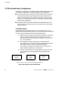
Installation Selecting an Installation Option In addition to the standard Powerware 9150, the UPS has an optional PDM. Use the following flow chart to decide which installation option is right for you. Do you have an optional PDM? Yes See “UPS with Optional PDM Installation” on page 25. No See the following section, “UPS Installation.
Installation Use the following procedure to connect utility power and load to the UPS: 1. Verify that the electrical connections to the installation site have been properly installed. Compare the circuit breaker ratings and cable sizes to the ones shown in the terminations table on page 24. 2. A user-supplied, readily-accessible, disconnection device must be incorporated in both the input and output wiring (see the following breaker ratings).
Installation Left Panel Screws Figure 5. Removing the UPS Panels 22 Powerware® 9150 User’s Guide : www.powerware.
Installation 6. Verify that the UPS battery breaker CB1 and optional CB2 are in the OFF position (see Figure 6). UPS ON/OFF Switch and Indicators ON OFF Input Conduit Access Terminal Block Output Conduit Access F1 Battery Neutral Fuse CB2 (Optional) CB1 External Internal Battery Battery Breaker Breaker Maintenance Bypass Switch Figure 6. UPS Front and Side View 7. Hardwire the input (TB1-1 through TB1-4) and output (TB1-6 through TB1-9) terminations for the UPS.
Installation Powerware 9150 Hardwired Terminations Wire Function Input p Output p Terminal Position* Upstream Circuit Breaker Suggested Wire Size** Ground TB1-1 L1/A TB1-2 70A 4 AWG L2/B TB1-3 70A 4 AWG Neutral TB1-4 2 AWG Ground TB1-6 8 AWG L1/A TB1-7 4 AWG L2/B TB1-8 4 AWG Neutral TB1-9 2 AWG Conduit Connection (Entry Size) 8 AWG 1-3/42 access hole for or 1-1/42 conduit 1-3/42 access hole for or 1-1/42 conduit *All terminal wire size ratings are 8 - 4 AWG, except TB1-4 a
Installation 9. Reinstall the UPS left side panel. (Do not reinstall the front panel at this time.) 10. Lower the leveling feet to prevent the UPS from rolling (does not apply for seismic mounting installations). 11. If you have additional battery cabinets, continue to “External Battery Cabinet Installation” on page 30. Otherwise, skip to “UPS Startup” on page 33.
Installation Left Panel Screws Figure 8. Removing the UPS Panels 26 Powerware® 9150 User’s Guide : www.powerware.
Installation 4. Verify that the UPS battery breaker CB1 and optional CB2 are in the OFF position (see Figure 9). ON OFF Terminal Block Output Conduit Landing F1 Battery Neutral Fuse CB2 (Optional) CB1 External Internal Battery Battery Breaker Breaker Maintenance Bypass Switch Figure 9. Connecting PDM Wiring to Terminal Block 5. Remove the lower rear panel of the UPS by unscrewing the six screws. Save the screws for reuse; the panel is no longer needed (see Figure 10). 6.
Installation Screws from UPS panel; 3 on each side reused for PDM Wire Cover for Output Conduit Landing Figure 10. Mounting the PDM to UPS Rear Panel 7. Insert the bushing (provided with the PDM packaging) into the output conduit landing. 8. Hardwire the input (TB1-1 through TB1-4) terminations for the UPS. See the following hardwired terminations table for specifications. See Figure 11 for a detailed view of the terminal blocks. 9.
Installation Powerware 9150 Hardwired Terminations for Optional PDM Wire Function Input Terminal Position* Upstream Circuit Breaker Ground TB1-1 L1/A TB1-2 70A 4 AWG L2/B TB1-3 70A 4 AWG Neutral TB1-4 Suggested Wire Size** Conduit Connection (Entry Size) 8 AWG 1-3/42 access hole for or 1-1/42 conduit 2 AWG Output for PDM Wire Color Ground TB1-6 Green/Yellow L1/A TB1-7 Black L2/B TB1-8 Red Neutral TB1-9 White 1-3/42 access hole for or 1-1/42 conduit *All terminal wire size
Installation 10. Connect the wire cover to the PDM using the two screws provided (see Figure 10). 11. Reinstall the UPS left side panel. (Do not reinstall the front panel at this time.) 12. Lower the leveling feet to prevent the UPS from rolling (does not apply for seismic mounting installations). 13. If you have additional battery cabinets, continue to the following “External Battery Cabinet Installation” procedure. Otherwise, skip to “UPS Startup” on page 33.
Installation CB2 CB1 Safety Wire Figure 12. EBC Front Panel 5. Verify that the circuit breakers CB1 and CB2 are in the OFF position on each battery cabinet. 6. Remove the cover plate on the rear of the UPS cabinet (see Figure 13). Pull the battery connector out of the UPS, cut the tie-wrap, and discard the cover plate. Pull the battery cable from the rear of the battery cabinet and plug it into the battery connector on the UPS rear panel. Rotate the EBC conduit fitting into position (90 angle up).
Installation EBC EBC EBC Cover Plate (for additional EBCs) UPS Battery Cable Battery Cable Cover Plate Battery Connector Figure 13. Connecting the EBC 7. If additional battery cabinets are used, remove the EBC cover plate on the first battery cabinet. Pull the battery connector out of the EBC, cut the tie-wrap, and discard the cover plate. Plug the battery cable from the second EBC into the battery connector of the first EBC and secure the cover plate. Follow this procedure for each battery cabinet.
Installation 10. Lower the leveling feet to prevent the EBC from rolling (does not apply for seismic mounting installations). 11. Continue to the following “UPS Startup” procedure. UPS Startup WARNING Only qualified service personnel (such as a licensed electrician) should perform the UPS installation and initial startup. Risk of electrical shock. Verify that UPS installation has been carried out correctly and the UPS ground has been connected.
Installation If the UPS does not start and an LED other than the UPS ON indicator is blinking, the UPS is in Automatic Configuration Mode (see page 36). CAUTION Do not rotate the Maintenance Bypass switch to the UPS position until the UPS ON, LINE ON, BYPASSED, and LOAD indicators illuminate; otherwise, it could cause a power loss to your equipment. 7. Turn the Maintenance Bypass switch to the UPS position. The BYPASSED indicator turns off when power transfers to the inverter.
Installation UPS Startup on Battery NOTE Before using this feature, the UPS must have been powered by utility power at least once so that the UPS can auto-detect the frequency (50 or 60 Hz). 1. Remove the front panel. Lift from the bottom of the panel and then pull out (see Figure 5 on page 22). 2. Verify that the Maintenance Bypass switch is in the UPS position. 3. Turn the UPS battery breaker CB1 and optional CB2 to the ON position.
Installation Configuring Voltage and Frequency The UPS automatically attempts to match the voltage and frequency to the existing utility. If the UPS is unsuccessful or if you want to bypass the automatic configuration, the voltage and frequency can be selected manually. Automatic Configuration Mode Automatic configuration is performed only during the initial UPS startup or during a bypass startup. The UPS attempts to match voltage and frequency to the existing utility.
Installation Manual Configuration Mode To change the nominal output voltage and frequency from the front panel: 1. If the UPS is operating in Normal Mode, turn off the UPS ON/OFF switch (the position). Then press and hold the RESET pushbutton on the LED panel while turning on the UPS ON/OFF switch (the | position). Continue to hold the RESET pushbutton until the LEDs begin to cycle right to left and then release. 2. One of the LEDs remains blinking.
Installation 38 Powerware® 9150 User’s Guide : www.powerware.
CHAPTER 4 OPERATION This chapter contains information on how to use the Powerware 9150, including UPS shutdown, maintenance bypass operation, and UPS communication. Control Panel Functions The control panel contains the UPS ON/OFF switch, the Battery Start pushbutton, and the LED panel. The control panel shows the status of the operation and generates an audible alarm (see Figure 14). The LED panel contains the UPS indicators and the RESET pushbutton (see Figure 15).
Operation Figure 15. LED Panel The following table shows the LED status and description. LED Status Description UPS ON On UPS is operating normally. Blinking UPS is starting up or is shut down and waiting for power to return. Off UPS is turned off and will not turn on automatically. On The utility voltage is acceptable for UPS and BYPASS operation. Off The utility voltage is not acceptable for BYPASS operation. The UPS may still be operating on utility power. On UPS is in Battery Mode.
Operation LED Status Description OVERTEMP On or Blinking One of the main UPS components is too hot or the fan has failed. SERVICE Blinking Battery failure, fan failure, or configuration error exists. Contact your service representative. See “Service and Support” on page 57. ALARM Blinking There is a UPS alarm condition. See Chapter 6, “Troubleshooting” on page 55 for additional information.
Operation The Powerware 9150 can operate in Normal, Bypass, or Battery Mode. The UPS automatically switches between these modes as required, and the UPS front panel indicates the current mode of operation. Normal Mode When the UPS is in Normal Mode, the UPS ON and LINE ON indicators illuminate. The LOAD indicator(s) display percentage of UPS load capacity being used by the protected equipment.
Operation UPS Shutdown To shut down the UPS: 1. Remove the front panel. Lift from the bottom of the panel and then pull out (see Figure 17). 2. Turn the Maintenance Bypass switch to the SERVICE or BYPASS position. 3. Turn off the UPS ON/OFF switch (the position). 4. Turn the UPS battery circuit breaker CB1 and optional CB2 to the OFF position. The UPS stops supplying power and is disconnected internally from the batteries. The load is powered by the utility. Powerware® 9150 User’s Guide : www.powerware.
Operation ON OFF UPS ON/OFF Switch and Indicators F1 Battery Neutral Fuse CB2 (Optional) CB1 External Internal Battery Battery Maintenance Bypass Switch Figure 17. UPS Breakers and Switches (Front Panel Removed) Using the Maintenance Bypass Switch The Maintenance Bypass switch is standard on all Powerware 9150 models and is used to bypass the UPS during maintenance or servicing. The Maintenance Bypass switch is located behind the front panel.
Operation WARNING : If the input frequency is not correct and the UPS is not synchronized to utility power (LINE ON indicator is off), the use of the Maintenance Bypass switch causes a break in the output voltage. Wait until the LINE ON indicator illuminates before using the switch. : Do not use the Maintenance Bypass switch if the UPS is configured as a frequency converter (50 Hz in/60 Hz out or 60 Hz in/50 Hz out); it could cause damage to the load. To operate the Maintenance Bypass switch: 1.
Operation Computer and Alarm Connections An interface for direct communication with your computer system is supplied in the UPS. The interface consists of two RS-232 serial data interfaces, four isolated alarm contacts, and remote emergency power-off (REPO). These interfaces are located beneath the control panel (see Figure 18). | ® X2 REPO 15-Pin Relay Interface 9-Pin Port for RS-232 (Female) 9-Pin Port for RS-232 (Male) Figure 18.
Operation ConnectUPS Mounting Bracket Communication Cables Figure 19. Hardware Connections RS-232 Serial Data Interfaces The Powerware 9150 is designed to fully comply with LanSafe III/ FailSafe III Power Management Software and OnliNet9 Strategic Power Management Software. If any other software is used, the pin configuration should be verified. The RS-232 interfaces use 9-pin, D-sub connectors. The information includes data about the utility, the load, and the UPS.
Operation 5 4 9 3 8 2 7 1 1 6 Female Connector (OnliNet or ConnectUPS) 2 6 3 7 4 8 5 9 Male Connector (LanSafe III/FailSafe III or Modem) Figure 20. 9-Pin Serial Port Use the female connector for a computer running OnliNet software or for a ConnectUPS Adapter. The communication settings are 19200 baud, 1 start bit, 8 data bits, No parity, and 1 stop bit. See the following table for pin assignments.
Operation Isolated Alarm Relay Interface The isolated alarm relay interface uses a 15-pin, male, 42D-sub connector. 1 2 9 3 10 4 5 11 12 6 7 13 14 8 15 Figure 21. 15-Pin Serial Port Relay Interface of Powerware 9150 Pin No.
Operation Remote Emergency Power-off Input REPO is used to shut down the UPS from a distance. This feature can be used for shutting down the load and the UPS by thermal relay, for instance in the event of room overtemperature. Remote shutdown wires are connected on connector X2 (see Figure 18 on page 46). The pins of connector X2 have been connected together. When this connection is open, the logic circuitry completely shuts down the UPS, thus preventing the power from supplying the load.
CHAPTER 5 SPECIFICATIONS Powerware 9150 Technical Specifications Rated Power 8 kVA, 10 kVA, 12.5 kVA at 0.7 power factor Technology Online, double-conversion topology with Static Bypass switch and 3-position Maintenance Bypass switch. Frequency independent operation. Input Voltage Range 85 - 146 Vac per phase Input Power Factor 0.
Specifications Powerware 9150 Model Specifications Model 12.5 kVA Input Current 54A 56A 52A 52A 49A Output Voltage 100/200V 110/220V 120/240V 120/208V 127/220V Output Current 52A 52A 52A 52A 52A Output kVA (line-line loads) 10.4 11.4 12.5 10.8 11.4 Output kVA (line-neutral loads) 10.4 11.4 12.5 12.5 13.2 Output kW 7.28 8.75 8.75 8.75 8.
Specifications Model 8 kVA Input Current 39A 40A 36A 36A 35A Output Voltage 100/200V 110/220V 120/240V 120/208V 127/220V Output Current 33.3A 33.3A 33.3A 33.3A 33.3A Output kVA (line-line loads) 6.7 7.3 8.0 6.9 7.3 Output kVA (line-neutral loads) 6.7 7.3 8.0 8.0 8.5 Output kW 4.7 5.6 5.6 5.6 5.
Specifications Environmental and Safety Specifications Ambient Temperature 0C to + 40C operating +15C to +25C recommended -10C to +40C storage with batteries -10C to +50C without batteries Ventilation Fan cooling, temperature uP monitored Altitude 3,281 ft (1000 m) operating without derating 41,012 ft (12500 m) during transportation Humidity 5 - 95% RH, noncondensing Audible Noise < 55 dBA at 1 meter distance Safety UL 1778, cUL EMC/RFI FCC class A Surges ANSI/IEEE C62.
CHAPTER 6 TROUBLESHOOTING The Powerware 9150 is designed for durable, automatic operation and also alerts you whenever potential operating problems may occur. Usually the alarms shown by the control panel do not mean that the output power is affected. Instead, they are preventive alarms intended to alert the user. Use the following troubleshooting chart to determine the UPS alarm condition. Indicator or Alarm Possible Cause Action ON BATTERY LED is on.
Troubleshooting Indicator or Alarm Possible Cause ALARM On or Blinkingg 1 short and 4 long beeps indicate a neutral fault. 10 short and 5 long beeps indicate a neutral fault at startup. Action Input Neutral must be connected. Contact qualified service personnel (such as a licensed electrician) electrician). 7 short and 1 long beep indicates a neutral fault at shutdown. ALARM blinking 3 short beeps p and 1 l long beep. b REPO initiated. None.
Troubleshooting Service and Support If you have any questions or problems with your UPS, call for service at one of the following telephone numbers and ask for a UPS technical representative: In the United States In Canada All other countries 1-800-365-4892 1-800-461-9166 1-919-870-3149 Please have the following information ready when you call for service: : Model number : Serial number : Version number (if available) : Date of failure or problem : Symptoms of failure or problem : Customer ret
Troubleshooting 58 Powerware® 9150 User’s Guide : www.powerware.
Powerware 9150 Limited Warranty (US Only) This limited warranty applies only to units installed in the fifty United States of America. Powerware Corporation warrants the electronics (Unit) to be free from defects in material and workmanship for a period of two years from the Date of Delivery or 30 months from the Date of Manufacture, whichever expires first.
`` 60 Powerware® 9150 User’s Guide : www.powerware.