® Powerware FERRUPS FE/QFE UPS User’s Guide 500 VA–18 kVA, 50 and 60 Hz
® Powerware FERRUPS FE/QFE UPS User’s Guide 500 VA–18 kVA, 50 and 60 Hz www.powerware.
Class A EMC Statements FCC Part 15 NOTE This equipment has been tested and found to comply with the limits for a Class A digital device, pursuant to part 15 of the FCC Rules. These limits are designed to provide reasonable protection against harmful interference when the equipment is operated in a commercial environment.
TABLE OF CONTENTS 1 Introduction . . . . . . . . . . . . . . . . . . . . . . . . . . . . . . . . . . . . . . . . . . . . . . . . . . . . 1 Identifying Your UPS . . . . . . . . . . . . . . . . . . . . . . . . . . . . . . . . . . . . . . . . . . . . . . . . . . . . . . . . . . 1 2 Safety Warnings . . . . . . . . . . . . . . . . . . . . . . . . . . . . . . . . . . . . . . . . . . . . . . . . 3 3 UPS Startup . . . . . . . . . . . . . . . . . . . . . . . . . . . . . . . . . . . . . . . . . . . . . . . . . . .
Table of Contents 6 Options . . . . . . . . . . . . . . . . . . . . . . . . . . . . . . . . . . . . . . . . . . . . . . . . . . . . . . . 49 Bypass Switches . . . . . . . . . . . . . . . . . . . . . . . . . . . . . . . . . . . . . . . . . . . . . . . . . . . . . . . . . . . . . Control Panel . . . . . . . . . . . . . . . . . . . . . . . . . . . . . . . . . . . . . . . . . . . . . . . . . . . . . . . . . . . . . . . Environmental Monitoring . . . . . . . . . . . . . . . . . . . . . . . . . . . . . . . . . .
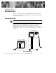
CHAPTER 1 INTRODUCTION Welcome to the growing Powerware9 FERRUPS uninterruptible power system (UPS) family. This UPS represents a breakthrough in the design of advanced, online UPSs. Identifying Your UPS NOTE Before starting up the UPS, verify that it has been installed according to the Powerware FERRUPS FE/QFE UPS (500 VA–18 kVA) Installation Guide. FERRUPS UPSs come in different sizes (see Figure 1). If your UPS is a 500 VA–3.1 kVA model, continue with “Startup for the FE and QFE 500 VA–3.
Introduction 2 Powerware® FERRUPS FE/QFE UPS (500 VA–18 kVA) User’s Guide : Rev A www.powerware.
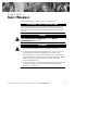
CHAPTER 2 SAFETY WARNINGS Read the following precautions before you install the UPS. IMPORTANT SAFETY INSTRUCTIONS SAVE THESE INSTRUCTIONS. This manual contains important instructions that you should follow during installation and maintenance of the UPS and batteries. Please read all instructions before operating the equipment and save this manual for future reference. DANGER This UPS contains LETHAL VOLTAGES. All repairs and service should be performed by AUTHORIZED SERVICE PERSONNEL ONLY.
Safety Warnings CAUTION : Batteries can present a risk of electrical shock or burn from high short-circuit current. Observe proper precautions. Servicing should be performed by qualified service personnel knowledgeable of batteries and required precautions. Keep unauthorized personnel away from batteries. : Proper disposal of batteries is required. Refer to your local codes for disposal requirements. : Never dispose of batteries in a fire. Batteries may explode when exposed to flame.
Safety Warnings ADVARSEL : Batterier kan udgøre en fare for elektrisk stød eller forbrændinger forårsaget af høj kortslutningsspænding. De korrekte forholdsregler bør overholdes. : Korrekt bortskaffelse af batterier er påkrævet. Overhold gældende lokale regler for bortskaffelsesprocedurer. : Skaf dig aldrig af med batterierne ved at brænde dem. Batterierne kan eksplodere ved åben ild.
Safety Warnings OPGELET : Batterijen kunnen gevaar voor elektrische schok of brandwonden veroorzaken als gevolg van un hoge kortsluitstroom. Volg de desbetreffende aanwijzingen op. : De batterijen moeten op de juiste wijze worden opgeruimd. Raadpleeg hiervoor uw plaatselijke voorschriften. : Nooit batterijen in het vuur gooien. De batterijen kunnen ontploffen.
Safety Warnings VARO : Akusto saattaa aiheuttaa sähköiskun tai syttyä tuleen, jos akusto kytketään oikosulkuun. Noudata asianmukaisia ohjeita. : Akusto täytyy hävittää säädösten mukaisella tavalla. Noudata paikallisia määräyksiä. : Älä koskaan heitä akkuja tuleen. Ne voivat räjähtää. Consignes de sécurité CONSIGNES DE SÉCURITÉ IMPORTANTES CONSERVER CES INSTRUCTIONS CE MANUEL CONTIENT DES CONSIGNES DE SÉCURITÉ IMPORTANTES DANGER! Cet onduleur contient des TENSIONS MORTELLES.
Safety Warnings ATTENTION! : Les batteries peuvent présenter un risque de décharge électrique ou de brûlure par des courts-circuits de haute intensité. Prendre les précautions nécessaires. : Une mise au rebut réglementaire des batteries est obligatoire. Consulter les règlements en vigueur dans votre localité. : Ne jamais jeter les batteries au feu. L’exposition aux flammes risque de les faire exploser. Sicherheitswarnungen WICHTIGE SICHERHEITSANWEISUNGEN AUFBEWAHREN.
Safety Warnings VORSICHT! : Batterien können aufgrund des hohen Kurzschlußstroms Elektroschocks oder Verbrennungen verursachen. Die entsprechenden Vorsichtsmaßnahmen sind unbedingt zu beachten. : Die Batterien müssen ordnungsgemäß entsorgt werden. Hierbei sind die örtlichen Bestimmungen zu beachten. : Batterien niemals verbrennen, da sie explodieren können.
Safety Warnings : Ãéá íá óõìöùíåß ìå ôá äéåèíÞ ðñüôõðá êáé ôïõò êáíïíéóìïýò êáëùäßùóçò, ôï ñåýìá äéáññïÞò ðñïò ôç ãç ïëüêëçñïõ ôïõ åîïðëéóìïý, ðïõ åßíáé óõíäåäåìÝíïò ìå ôçí Ýîïäï ôïõ óõãêåêñéìÝíïõ UPS, äåí ðñÝðåé íá åßíáé ìåãáëýôåñï áðü 1,5 mA. : ÐÑÏÓÏ×Ç Ïé óõóóùñåõôÝò ìðïñåß íá ðñïêáëÝóïõí çëåêôñïðëçîßá Þ Ýãêáõìá áðü õøçëü ñåýìá âñá÷õêõêëþìáôïò. ËáìâÜíåôå ôéò êáôÜëëçëåò ðñïöõëÜîåéò. : Áðáéôåßôáé óùóôÞ äéÜèåóç ôùí óõóóùñåõôþí. Äåßôå ôïõò ôïðéêïýò êáíïíéóìïýò ðïõ áöïñïýí ôéò áðáéôÞóåéò äéÜèåóÞò ôïõò.
Safety Warnings : Per ridurre il rischio di incendio o di scossa elettrica, installare il gruppo statico di continuità in un ambiente interno a temperatura ed umidità controllata, privo di agenti contaminanti conduttivi. La temperatura ambiente non deve superare i 40°C. Non utilizzare l’unità in prossimità di acqua o in presenza di umidità eccessiva (95% max).
Safety Warnings : Alt utstyr som er forbundet med utgangen av denne UPS’en må ikke ha en sterkere total lekkasjestrøm enn 1,5 milliampere for å være i overensstemmelse med internasjonale standarder og forkablingsbestemmelser. FORSIKTIG : Batterier kan forårsake elektriske støt eller forbrenning på grunn av høy kortslutningsstrøm. Følg instruksene. : Batterier må fjernes på korrekt måte. Se lokale forskrifter vedrørende krav om fjerning av batterier.
Safety Warnings PERIGO : As baterias podem apresentar o risco de choque elétrico, ou queimaduras provenientes de alta corrente de curto-circuito. Observe as instruções adequadas. : Siga as instruções apropriadas ao desfazer-se das baterias. Consulte os códigos do local para maiores informações sobre os regulamentos de descarte de produtos. : Nunca jogue as baterias no fogo, porque há risco de explosão.
Safety Warnings : Для обеспечения соблюдения требований международных стандартов и требований к разводке электрических цепей, суммарная величина тока утечки на землю всего оборудования, подключенного к выходу ИБП, не должна превышать 1,5 миллиампера. ОСТОРОЖНО : Аккумуляторы могут вызвать опасность поражения электрическим током или ожога от тока короткого замыкания. Соблюдайте соответствующие меры предосторожности. : Необходимо соблюдать правила утилизации аккумуляторов.
Safety Warnings : Para reducir el riesgo de incendio o de choque eléctrico, instale este SIE en un lugar cubierto, con temperatura y humedad controladas, libre de contaminantes conductores. La temperatura ambiente no debe exceder los 40°C. No trabaje cerca del agua o con humedad excesiva (95% máximo).
Safety Warnings : Minska risken för brand eller elektriska stötar genom att installera denna UPS-enhet inomhus, där temperatur och luftfuktighet är kontrollerade och där inga ledande föroreningar förekommer. Omgivande temperatur får ej överstiga 40°C. Använd inte utrustningen nära vatten eller vid hög luftfuktighet (max 95 %).
CHAPTER 3 UPS STARTUP This section provides step-by-step instructions for starting the Powerware FERRUPS UPS. Follow these procedures closely to avoid potential damage to your equipment or the UPS and to protect yourself and others from hazardous operating conditions. Startup for the FE and QFE 500 VA–3.1 kVA UPS To start the FE and QFE 500 VA–3.1 kVA UPS, use the following steps: 1. Confirm the equipment to be protected by the UPS is powered off. 2.
UPS Startup 3. The AC LINE indicator illuminates (see Figure 2). NOTE The AC LINE indicator does not illuminate for FE models with serial numbers 25000 and greater until the UPS ON/OFF switch is turned to the ON position. AC LINE READY CHARGING BATTERY POWER ALARM Figure 2. Front Panel Indicators 4. If you have an external battery cabinet with a DC switch, turn the switch to the ON position. 5. Turn the UPS ON/OFF switch to the ON position.
UPS Startup Startup for the FE and QFE 4.3–18 kVA UPS To start the FE and QFE 4.3–18 kVA UPS, use the following steps: 1. Confirm the equipment to be protected by the UPS is powered off. 2. For Plug-Receptacle UPSs: Verify that the AC input power is off at the service panel. Plug the UPS power cord into a power outlet. NOTE If the plug does not match your receptacle outlet, ask your electrician to install the proper outlet.
UPS Startup NOTE If the ALARM indicator is on, read the alarm message on the control panel display, turn the ON/OFF and DC switches to the OFF position, and call your service representative. For Plug-Receptacle UPSs: Turn the AC input power on at the service panel. The AC LINE indicator illuminates. After a few seconds, the UPS switches from battery power to AC input power. The BATTERY POWER indicator turns off. For Hardwired UPSs: Turn the AC line disconnect switch to the ON position.
UPS Startup The date is parameter 10. To display the date, follow these steps: Press this key: [DISPLAY] [1][0] [ENTER] [PROGRAM] Display shows: 'LVSOD\ 'LVSOD\ 'DWH 3JP 7. If your FERRUPS UPS is configured to use an external battery cabinet, you must program the battery capacity in ampere-hour (Ah) for the total number of battery packs used in the UPS. If you purchased one of the FERRUPS battery pack options available from Powerware, select the Ah value from Table 1.
UPS Startup Table 1.
UPS Startup Rear Panels This section shows the rear panels of the FERRUPS models. RS-232 Communication Port Alarm Silence Switch On/Off Switch Power Cord Output Receptacles Figure 3. FERRUPS 500–850 VA UPS Rear Panel RS-232 Communication Port On/Off Switch Alarm Silence Switch Output Receptacles Figure 4. FERRUPS 1.15–1.4 kVA Rear Panel Powerware® FERRUPS FE/QFE UPS (500 VA–18 kVA) User’s Guide : Rev A www.powerware.
UPS Startup ON/OFF Switch RS-232 Communication Port Alarm Silence Switch Output Receptacles Figure 5. FERRUPS 1.8–3.1 kVA Rear Panel Receptacle Panel (Optional for 7 kVA) RS-232 Communication Port RS-232 Communication Port Optional Receptacle Panel 4.3–5.3 kVA Models 7–18 kVA Models Figure 6. FERRUPS 4.3–18 kVA Rear Panels 24 Powerware® FERRUPS FE/QFE UPS (500 VA–18 kVA) User’s Guide : Rev A www.powerware.
CHAPTER 4 OPERATION This section describes: : : : : : The UPS front panel indicators Using the control panel Automatic system testing Parameters Shutting down the UPS Front Panel Indicators The UPS front panel indicators indicate how the UPS is operating and also alert you of potential power problems. Figure 7 shows the UPS front panel indicators. Table 2 explains the status of each indicator. AC LINE READY CHARGING BATTERY POWER ALARM Figure 7.
Operation Table 2. Indicator Status Indicator Status AC LINE On The UPS is getting power from the AC input power source. NOTE The AC LINE indicator does not illuminate for FE models with serial numbers 25000 and greater until the UPS ON/OFF switch is turned to the ON position. Off : : : : : Flashing READY CHARGING 26 Not applicable. The UPS is ready to provide battery backup power when needed.
Operation Using the Control Panel The control panel comes with all FE/QFE 4.3–18 kVA models. If you have an FE/QFE 500 VA–3.1 kVA, you may have ordered the control panel as an option (refer to TIP 407 to connect the control panel). The control panel is attached to the front of the UPS with a 6-ft (1.8m) cable, providing hand-held operation.
Operation Table 3. Operating Modes Operating Mode How to Select It What It Means Off Press [CTRL]-[1] [ENTER] [ENTER]. The UPS does not provide power to your equipment, but you can still use the control panel if battery power is present. The READY indicator is off. Auto Press [CTRL]-[2] [ENTER] [ENTER]. This is the normal operating mode. The UPS conditions AC input power and provides the conditioned power to your equipment. The UPS is ready to switch to battery power if necessary.
Operation Displaying and Changing Parameters The names of the first 11 parameters appear in green on the top of the number keys. To display a parameter, press [DISPLAY], the parameter number, and [ENTER]. For example, to display parameter 0 (time), follow these steps: Press this key: [DISPLAY] [0] [ENTER] Display shows: 'LVSOD\ 'LVSOD\ 7LPH To change a parameter, display it first. Then, press [PROGRAM], enter the new value for the parameter, and press [ENTER].
Operation After approximately two seconds, the control panel shows the same display it showed before you unlocked it. If you enter the wrong unlock number, the control panel displays .H\SDG /RFNHG for two seconds, and the control panel remains locked. Using the Configuration Menu The control panel includes a Configuration Menu that lets you adjust its baud rate and brightness, turn the beeper on or off, turn on and off the click you hear when you press keys, and control other features.
Operation Automatic System Test The UPS performs an automatic system test every seven days to test the memory, batteries, and inverter. During the system test, the BATTERY POWER and READY indicators Flash. For the results of the last system test, you can display parameter 26 (see page 35). Logic Test First, the UPS checks its memory. If it finds a problem, the UPS sounds alarm O, Memory Check (– – –). See “Alarms” on page 59.
Operation Parameters Table 4 shows the first 26 parameters. You can view or reset the parameters using the control panel or a terminal or computer. If you plan to view or change parameters from the control panel, see “Using the Control Panel” on page 27 for instructions. If you plan to view or change parameters from a terminal or computer that you have connected to the RS-232 port, see “Entering Commands from a Terminal or Computer” on page 44.
Operation Parameter Number Sample Display Password Parameter Name Explanation (Short Form) 3 03 --Reserved-- 4 04 I Out 3.1 Service acampsiout (o) 5 05 VA Out 374 Change Not Allowed vaout (va) Volt-Amps Out. The total “apparent power” your equipment is drawing from the UPS. This value is based on parameter 2 multiplied by parameter 4, and should be less than or equal to the VA or kVA rating of the UPS. See VA Limit, parameter 19. 6 06 I Batt 0.0 Service ibatt (ib) Battery Current.
Operation Parameter Number Sample Display Password 14 14 XfmrTemp 28c Change Not Allowed xfmrtemp (xt) The temperature of the transformer. The UPS sounds an alarm and shuts down if this value is too high. NOTE This parameter is only active on some models; for other models, the display always shows -63c. 15 15 Unit ID Network #1 UPS None (See “Entering Passwords” on page 28.) unitident (id) UPS ID. An identification string that can be configured for use with your network.
Operation Parameter Number Sample Display Password Parameter Name Explanation (Short Form) 24 24 Inverter Log L 0319 2127 1215 Change Not Allowed inverterlog (il) A record of the date, time, duration and reason for the last 20 inverter (battery power) runs (see “Alarm and Inverter Logs” on page 62). 25 25 Alarm Log A 0319 2127 1215 Change Not Allowed alarmlog (al) A record of the date, time, duration and reason for the last 20 alarms (see “Alarm and Inverter Logs” on page 62).
Operation CAUTION When AC input voltage is present, the UPS system can provide output voltage even though its batteries are disconnected. To confirm that there is no UPS output voltage, always disconnect the AC input source; if the UPS has one or more separate battery cabinets, open the DC disconnect switch on each battery cabinet or disconnect the battery cabinet from the UPS. 1. UPSs with no bypass switch: Turn off the protected equipment. Continue to Step 2.
Operation 4. 500 VA–3.1 kVA: If you have a battery cabinet that has a DC switch on the front, turn the switch to the OFF position. If your battery cabinet does not have a DC switch on the front, unplug the connector between the battery cabinet(s) and the UPS; be sure to reconnect this connector before you start the UPS again. 4.3–18 kVA: Unlock the lock in the center of the front panel and remove the panel. If there is a DC switch behind the panel, turn it to the OFF position.
Operation 38 Powerware® FERRUPS FE/QFE UPS (500 VA–18 kVA) User’s Guide : Rev A www.powerware.
CHAPTER 5 COMMUNICATION The FERRUPS UPS is capable of full-duplex communication and can communicate with a computer, a Local Area Network (LAN), or a multi-user computer system. If your system comes with UPS monitoring and automatic shutdown software, the FERRUPS UPS can communicate with that software. If your system does not have software, you can use the CheckUPS II Power Management Software included on the Powerware Software Suite CD-ROM.
Communication Communication Port The communication port cable pins are identified in Figure 9 and the pin functions are described in Table 5. Figure 9. Communication Port Table 5. Communication Port Pin Functions Pin Function Function 2 Transmit Data (in) 3 Receive Data (out) 4 Request to Send 5 Clear to Send 6 +12V Level (0.01A) when the UPS is operating 7 Signal Ground 11 Contact opens when on inverter 12 Contact closes when on inverter 13 Common Inverter Signal Contact 14 +12V, 0.
Communication Connecting a Terminal or Computer to the RS-232 Port CAUTION Do not make connections to the RS-232 communication port if the UPS is connected to a positive ground battery system. The RS-232 ground must be isolated or equipment damage will result. For help, contact your service representative. If you are connecting a terminal to the RS-232 port, the terminal must be capable of serial communication.
Communication Figure 10. DB-9 to UPS Pinout Figure 11. DB-25 to UPS Pinout 2. Connect the cable from the RS-232 port on the back of the UPS to the serial port on your terminal or computer. 3. Your terminal or computer should be set to: 1200 baud, 8 bits, No parity, 1 stop bit, and full duplex. The terminal or terminal emulation software should also be set to full duplex. If you are using a terminal, note that the FERRUPS UPS supports the Televideo9 900 series, ADM3A and WYSE9 50 emulation.
Communication Table 6. DB-25 Port Settings Specification Standard Setting Adjustable to Connector 25 pin D (female) wired as DCE. Format ASCII, 8 bits, 1 stop bit. Most significant bit set to 0. Standard setting or 7/8 bits, 1/2 stop Baud Rate 1200 50–38400 Parity None Odd, Even, or None Duplex Full Full or Half 4. Turn your terminal on or run your terminal emulation software. Then press [ENTER] on your keyboard; a prompt appears on the screen.
Communication Entering Commands from a Terminal or Computer To monitor or control the FERRUPS UPS from a terminal or computer, simply type in one of the commands and press [ENTER] (see Table 8). Use the following command syntax: : type the command in uppercase or lowercase : use the entire command or the short form (you can also abbreviate the command as long as you include the letters in the short form : use a semicolon to separate more than one command on a line Table 8.
Communication Command Short Form Password date da None* Displays system time and date. To set the date, enter date [month]/[day]/[year]. delay dl None Delays next command when you enter a number after delay. Each unit represents 2.5 milliseconds, so delay 1 would cause a 2.5 millisecond delay. For a 1-second delay, enter delay 400.
Communication Command Short Form Password Function paramkeywords pk password pw None program pr Depends on parameter password remote rm None Configures the RS-232 port so the connected terminal works like a control panel. shutdown or shutdown autostart sd None* sd a Shuts down the UPS output in 60 seconds (if you enter shutdown alone) or the number of seconds you specify after the command. The READY indicator flashes until the UPS shuts down.
Communication Command Short Form Password Function systemtest stst None* Starts a system test of the logic, inverter and battery. time t None Shows the current UPS time. To set the time, enter [hour]:[minutes] after the command. unshutup u None Turns audible alarm back on. *If you change parameter 39 to “Yes,” this command requires a User password.
Communication To restart the UPS, break the connection between Pins 6 and 21 (or between Pins 18 and 21) at the UPS’s RS-232 port. Then, follow the steps in “Startup” on page 17 for your model. Note that the 12V level on Pin 6 or Pin 18 is only available when the UPS is operating. You can change the type of signal that the UPS responds to and how quickly it responds. You can also set up the UPS to restart automatically when the shutdown signal stops.
CHAPTER 6 OPTIONS Powerware offers many options for your FERRUPS UPS. If you would like more information, contact your local Powerware office or distributor. Bypass Switches If your UPS does not have a plug, a bypass switch lets you transfer your protected equipment to direct AC input power conveniently when it’s time to service the UPS. Contact your local Powerware office or distributor for recommendations and additional information on the different bypass switches.
Options 50 Powerware® FERRUPS FE/QFE UPS (500 VA–18 kVA) User’s Guide : Rev A www.powerware.
CHAPTER 7 MAINTENANCE NOTE Technicians must observe important safety precautions while performing these checks. The FERRUPS UPS is designed to provide years of trouble-free operation. Its internal control system checks the batteries and inverter periodically to ensure reliable operation. In fact, you’ll probably find that your FERRUPS system requires less maintenance than any of your other computer peripherals.
Maintenance 52 Powerware® FERRUPS FE/QFE UPS (500 VA–18 kVA) User’s Guide : Rev A www.powerware.
CHAPTER 8 SPECIFICATIONS Table 9. FE and QFE 500 VA–3.1 kVA Model 500 VA/ 350W 700 VA/ 500W 850 VA/ 600W 1.15 kVA/ 800W 1.4 kVA/ 1 kW 1.8 kVA/ 1.25 kW 2.1 kVA/ 1.5 kW 3.1 kVA/ 2.2 kW AC Input Voltage and Current, Standard Charger FE: 120 Vac 208 Vac1 220 Vac 240 Vac1 QFE: 120 Vac 220 Vac 230 Vac 240 Vac 4.6A 2.4A 2.3A 2.1A 4.4A 2.6A 2.5A 2.4A 5.6A 2.8A 2.7A 2.5A 5.8A 3.9A 3.8A 3.5A 6.6A 3.7A 2.5A 3.2A 7.0A 4.4A 4.2A 4.0A 8.9A 5.0A 4.6A 4.2A 8.4A 4.9A 4.6A 4.4A 11A 6.0A 5.8A 5.3A 11A 5.7A 5.
Specifications Model Runtime (minutes) QFE Full Load: Half Load: FE Full Load: Weight : Without Battery: 60 Hz Models: 50 Hz Models: With Battery: 60 Hz Models: 50 Hz Models: Dimensions (H x W x D) 500 VA/ 350W 700 VA/ 500W 850 VA/ 600W 1.15 kVA/ 800W 1.4 kVA/ 1 kW 1.8 kVA/ 1.25 kW 2.1 kVA/ 1.5 kW 3.1 kVA/ 2.2 kW 9 25 9 14 35 11 11 28 9 18 48 8 14 37 11 11 30 11 9 25 9 14 35 14 44 lb 22.2 kg 46 lb 25 kg 51 lb 27.7 kg 92 lb 41.7 kg 106 lb 45.4 kg 120 lb 58.1 kg 132 kg 63.
Specifications Model 4.3 kVA/ 3 kW 5.3 kVA/ 3.7 kW 7 kVA/ 5 kW 10 kVA/ 7.5 kW 12.5 kVA/ 10 kW 18 kVA/ 15 kW Output Voltage and Maximum Output Current3 FE: 120 Vac 208 Vac 220 Vac 240 Vac QFE: 220 Vac 230 Vac 240 Vac 34A 20A 19A 17A 19A 18A 17A 44A 26A 24A 22A 23A 22A 21A 58A 34A 31A 29A 31A 30A 28A 82A 48A 46A 41A 45A 43A 41A 103A 58A 55A 51A 56A 52A 51A 149A 84A 82A 73A 84A 76A 73A Efficiency On AC Line 90% 90% 90% 90% 91% 92% On Line BTU/hour: kW/hour: 1138 .333 1403 .411 1896 .
Specifications Table 11. Electrical Input and Output Nominal Frequency Online: 60 Hz (FE) or 50 Hz (QFE) with nominal power line grid stability of ±0.005 Hz. On inverter: 60 Hz (FE) or 50 Hz (QFE) ±0.03 Hz. Output frequency tracks input line frequency up to limit, which is adjustable from ±0.01 Hz to ±3.00 Hz. Inverter turns on if line frequency exceeds the selected limit. Regulation ±3% load regulation (under any line, load, or battery condition to within -8.
Specifications Table 12.
Specifications 58 Powerware® FERRUPS FE/QFE UPS (500 VA–18 kVA) User’s Guide : Rev A www.powerware.
CHAPTER 9 TROUBLESHOOTING When your FERRUPS UPS detects an alarm condition, the UPS displays the alarm with the following indications: : the ALARM indicator on the front panel (and the control panel if you have one) illuminates : sounds an audible alarm : displays an alarm message on the control panel (if you have one). NOTE If the control panel does not display the message, press [CLEAR] until you reach the scrolling display. Alarms When an alarm occurs, follow these steps: 1.
Troubleshooting Table 14. Alarms Letter Audio Code Alarm Message What It Means What To Do A :– Low Battery The UPS has shut down after running on battery and discharging the batteries. Wait for AC input power to be restored. When AC input power returns, turn on the UPS. The CHARGING indicator illuminates as the UPS begins recharging batteries. B –::: Near Low Battery The battery voltage has reached the Near Low Battery setpoint.
Troubleshooting Letter Audio Code Alarm Message What It Means What To Do J :––– User Test Alarm The user is testing the alarm feature. To start the user test alarm from the control panel, press [CTRL]-[8] [ENTER] [ENTER]. Repeat the procedure to turn the alarm off. K –:– Hi Transfmr Temp The transformer temperature is too high. If The UPS may have shut down; if so, the temperature reaches a preset point, the contact your service representative. If the UPS shuts down.
Troubleshooting Letter Audio Code Alarm Message T – Call Service W :–– Fan Alarm What It Means What To Do The UPS has detected a problem that requires service. The UPS shuts down. Contact your service representative. The fan has stopped. The UPS may have shut down; if so, contact your service representative. If the UPS has not shut down, shut down your equipment or bypass the UPS; then, turn the UPS off and contact your service representative.
Troubleshooting Each log entry consists of four pieces of information: the alarm code, the date (month/day) of the alarm, the time (in 24-hour time) and the duration (in hours and minutes). For instance, one entry might look like this: B 0205 1017 0005 In this example, “B” means the alarm was “Near Low Battery” (see “Alarms” on page 59); if alarm B was active, there would be an asterisk (*) after “B.” “0205” means the alarm occurred on February 5 (2/5). “1017” means the alarm occurred at 10:17 a.m.
Troubleshooting Table 15. Inverter Codes Inverter Code Meaning Explanation T System Test B Brownout AC input voltage was too low. L Line Loss AC input power was lost. M Manual The inverter was started manually. F Frequency R Reset UPS went to inverter to test the batteries. Input frequency was too high or too low. A system reset was performed.
Troubleshooting Reading the Inverter Log from a Terminal or Computer To display the Inverter Log on a terminal or computer, you can use the inverterlog or logs command (see “Entering Commands from a Terminal or Computer” page 44). These commands display up to 20 log entries in a table.
Troubleshooting Service and Support If you have any questions or problems with the UPS, call your Local Distributor or the Help Desk at one of the following telephone numbers and ask for a UPS technical representative.