
User Manual

Model 535 Operating Instructions
82 E. Main Street Suite 3.14 • Webster, NY 14580
Tel: 585-872-9350 • Fax: 585-872-2638
sales@piecal.com • http://www.piecal.com/
Practical Instrument Electronics, Inc. Copyright 2011. All rights reserved.
535-9002 Rev G 7/13/11
6-8
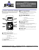
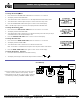
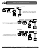
2 Wire Transmitter Simulate
Substitute the Model535 for a 2 wire transmitter. Use
the EZ-Dial Knob and EZ-Check Switch to adjust loop
current. At least 2 volts of loop power is required, else
the display flashes “CHECK LOOP SUPPLY.”
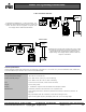
Source Volts
The Model 532 sources 0.000-24.000 volts. This is useful
for powering transmitters and receiver equipment. Use
the EZ-Dial Knob and EZ-Check Switch to adjust
output voltage. The display flashes “LOW Ω” when the
output is overloaded.
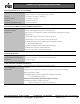
Specifications
General Specifications:
Unless otherwise indicated all specifications are rated from a nominal 23 °C, 70 % RH for 1 year from calibration with >1 MΩ load
on external banana jack access to 10 Ω current sense (Model 535A).
Operating Temperature Range -20 to 60 °C (-5 to 140 °F)
Storage Temperature Range -30 to 60 °C (-22 to 140 °F)
Relative Humidity Range
10 % ≤RH ≤90 % (0 to 35 °C), Non-condensing
10 % ≤RH≤ 70 % (35 to 60 °C), Non-condensing
Size 7.00 X 3.30 X 2.21 inches (177.8 x 83.8 x 56.1mm)
Weight 14.0 oz (397 grams)
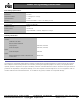
Battery
4 - AA Alkaline Optional 120 VAC 50/60 Hz AC adaptor included
Miscellaneous Low battery indication with nominal 1 hour of operation left
Over-voltage protection to 120 Vrms (rated for 30 seconds) or 240 Vrms (rated for 15
seconds)
Bar graph display with 1% resolution of 4-20/10-50 mA signal scale
High contrast graphic liquid crystal display with 0.45” (11.4 mm) high digits