Control Concepts Model 1022 / 1025 Power Control System Instruction Manual Another quality product from: 7128 Shady Oak Road Eden Prairie, MN 55344 USA (952) 949-9009 Fax (952) 949-9559 www.researchinc.
CONTROL CONCEPTS, INC. 2 YEAR LIMITED WARRANTY CONTROL CONCEPTS, INC. warrants that the products delivered will be as described in the sales order or contract. CONTROL CONCEPTS, INC. warrants to the original user that CONTROL CONCEPTS, INC. products will be free from defects in materials and workmanship for a period of two (2) years after the date CONTROL CONCEPTS, INC. ships such products. If any CONTROL CONCEPTS, INC.
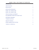
MODEL 1022 & 1025 TABLE OF CONTENTS DESCRIPTION 1 SPECIFICATIONS 1 INSTALLATION 2 INSTALLATION DRAWINGS 3 MODEL 1022 CONNECTIONS 5 MODEL 1025 CONNECTIONS 5 ZERO AND SPAN ADJUSTMENTS 6 RECOMMENDED SPARE PARTS AND FUSES 6 REFERENCE DRAWINGS 6 TROUBLE SHOOTING 7 MANUFACTURED BY 7 MODEL NUMBER IDENTIFICATION 8 THEORY OF OPERATION 8 MODEL 1022 & 1025 05/10/2007
DESCRIPTION The models 1022 and 1025 are single-phase phase-angle SCR power controllers. The controllers are the same except the 1022 accepts command signals of 0/5Vdc, 0/10Vdc or a potentiometer signal. The model 1025 accepts a 4/20mA command signal. Both controllers control the RMS voltage to the load proportional to the command signal, independent of line voltage hanges.
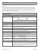
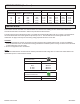
SPECIFICATIONS (Continued) SURGE CURRENT RATING KW Continuous RMS rating RMS 1 Second Peak 1 Cycle (Non-Repetive) I^2 t rating 120 Vac 240 Vac 277 Vac 480 Vac 575 Vac 10 20 30 40 70 22 40 80 150 150 140 250 625 1000 1000 81 260 1620 4150 4150 1.20 2.40 3.60 4.80 8.40 2.40 4.80 7.20 9.60 16.80 2.77 5.54 8.31 11.08 19.39 4.80 9.60 14.40 19.20 33.60 5.75 11.50 17.25 23.00 40.
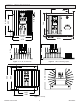
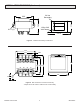
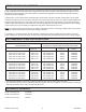
INSTALLATION DRAWINGS 5.50 0.20 (4) 1.00 0.30 7.50 4.00 6.00 1.50 0.20 (4) 8.50 3.70 4.20 4.375 4.75 Figure 1. 10, 20, 30 & 40 Amp. Figure 2. “-MO1” Mounting Option. 7.50 8.00 9.00 0.32 (4) 6.00 9.25 MODEL 1022 & 1025 Figure 3. 70 Amp.
INSTALLATION DRAWINGS (Continued) 1.62 1.19 24 Vac Secondary 2.00 120 or 240 Volt Primary 0.177 (2) 2.375 Figure 4. 120/240 Volt Primary Transformer. 2.99 2.50 0.245 0.375 H1 H2 H3 2.70 H4 1.75 2.50 3.25 X4 X2 X3 X1 2.99 0.44 0.22 Figure 5. 480 Volt across H1 and H4 of Primary. Jumper across X2 & X3 to create 24 Vac on Secondary.
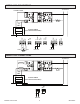
MODEL 1022 CONNECTIONS CONTROL SIGNAL CONNECTIONS TO SUPPLY LOAD 24 VAC CW POT 24 VAC 5 CCW W CW 24 VAC 0/10 Vdc + 0/5 Vdc + W CCW 5 CCW W CW 24 VAC 5 CCW W CW TRANSFORMER (NO PHASING REQUIRED) MODEL 1025 CONNECTIONS TO SUPPLY LOAD 24 VAC 24 VAC TRANSFORMER (NO PHASING REQUIRED) + 4/20 mA MODEL 1022 & 1025 05/10/2007
ZERO AND SPAN ADJUSTMENTS The zero and span adjustments have been factory adjusted to provide zero load voltage when the minimum command signal is applied and to provide rated output voltage to the load when the maximum command signal is applied. Further adjustment of these settings should not be required. If it is desired to readjust the zero and span settings the following procedures should be followed.
TROUBLE SHOOTING CAUTION: High voltage exists on the supply and load terminals of this controller and may exist on other equipment located near the controller. Use extreme caution to avoid electrical shock. The LED located on the controller circuit can be used to aid in determining problems. This LED varies in intensity proportional to the command signal and therefore should be proportional to the load voltage.
MODEL NUMBER IDENTIFICATION 102X-VV-AA [-SCXXX] [-MOXX] X = 2 for 1022, 5 for 1025 1022 (0/5Vdc, 0/10Vdc or POT control) 1025 (4/20mA input) VV = Rated voltage: 12 = 120Vac 24 = 240Vac 48 = 480Vac 57 = 570Vac AA = Rated amps: 10, 20, 30, 40, or 70 amps Note: The addition of "-SCXXX" implies that the controller has been modified to have a different input command. For example, a "-SC1/5Vdc" implies the controller has been modified to operate with a 1/5Vdc control signal.