
Instruction Manual

MODEL 1022 & 1025 1 05/10/2007
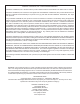
DESCRIPTION
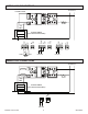
The models 1022 and 1025 are single-phase phase-angle SCR power controllers. The controllers are the same except
the 1022 accepts command signals of 0/5Vdc, 0/10Vdc or a potentiometer signal. The model 1025 accepts a 4/20mA
command signal.
Both controllers control the RMS voltage to the load proportional to the command signal, independent of line voltage
hanges. The controllers include soft-start and missing cycle detection which on power interruptions of one half cycle or
more sets the load voltage to zero and then increases the load voltage to the desired voltage at a predetermined rate.
his eliminates inrush currents that can occur due to loads with a low cold resistance or because of saturation when a
transformer is used between the controller and the load.
The command signal is electrically isolated from line and load voltages and all are electrically isolated from the heat sink.
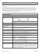
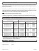
SPECIFICATIONS
CONTROL MODE: Single-phase; Phase-angle; RMS value of the voltage applied to the load
COMMAND SIGNAL: SIGNAL INPUT IMPEDANCE
Model 1022 0/5 Vdc 100K
0/10 Vdc 200K
Potentiometer 200K
(1K pot recommended, 20K permissible)
Model 1025 4/20 mA 200 Ohms
CONTROL RANGE: 6 to 97% of line voltage typical.
LINEARITY: RMS load voltage is linear within 2% of span of the command signal.
ZERO AND SPAN
ADJUSTMENTS:
User adjustable over range of +/- 20% of span.
ISOLATION: Dielectric strength input/line & load voltage/heatsink 4000V (RMS).
Insulation resistance input/line & load voltage/heatsink 10^10 ohms.
Maximum capacitance input to output 8pf.
COOLING: Convection
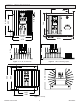
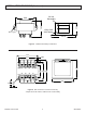
MOUNTING: Must be mounted on vertical surface with fins vertical. Unit may be mounted
adjacent to each other. Heatsink is electrically isolated.
LINE VOLTAGE: 120, 240, 480 or 575 Vac +10%, -20% 50/60 Hertz
DIAGNOSTIC INDICATOR: The intensity of an LED varies as a function of the command signal. Feature
provides a quick and safe means to check controller operation.
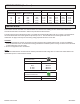
PHYSICAL: Weight: 10 - 40 Amp 2 lbs 70 Amps 6 lbs
Dimensions: Refer to installation drawings.
ENVIRONMENT: Operating: 0 to 55° C (32 to 131° F)
Storage: -40 to 80° C (-40 to 176° F)
Humidity: 0 to 95% Non-condensing
DV/Dt AND TRANSIENT
VOLTAGE PROTECTION:
200 volts/usec minimum
A dv/dt snubber and a metal oxide varistor (MOV) are provided to protect against
high frequency transients (dv/dt) and voltage spikes.
DISSIPATION: 1.5 watt per amp of controlled current
RECOMMENDED FUSING: Special semiconductor fuses are not required. It is advised that the controller and
load be protected with fast acting class ‘T’ fuses such as Bussmann type JJN (300V)
or JJS (600V) fuses. Control Concepts maintains an inventory of fuses and fuse
holders for your convenience. It is recommended that a fuse rated 120 to 125% of
maximum load current be selected.