
Instruction Manual

MODEL 1022 & 1025 2 05/10/2007
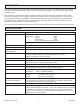
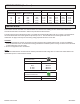
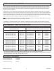
SPECIFICATIONS (Continued)
SURGE CURRENT RATING KW
Continuous
RMS rating
RMS 1
Second
Peak 1 Cycle
(Non-Repetive)
I^2 t rating 120 Vac 240 Vac 277 Vac 480 Vac 575 Vac
10
20
30
40
70
22
40
80
150
150
140
250
625
1000
1000
81
260
1620
4150
4150
1.20
2.40
3.60
4.80
8.40
2.40
4.80
7.20
9.60
16.80
2.77
5.54
8.31
11.08
19.39
4.80
9.60
14.40
19.20
33.60
5.75
11.50
17.25
23.00
40.25
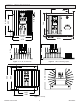
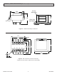
INSTALLATION
The controller must be mounted on a vertical surface such that the heat radiating fins are vertical and located in an
environment that will not exceed 55°C and that is protected from dirt and dust.
The wiring must be per local electrical codes. The supply and load terminals will accept up to # 6 wire. The terminals for
the circuit transformer and control signals accept wire up to # 14. The terminals for the control signals and circuit
transformer are plug-in and may be removed by pulling perpendicular to the circuit card.
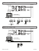
CAUTION:
1. The circuit transformer must be connected to the same supply as the controller and the load. A common installation
error has been that of the circuit transformer being powered from a different phase or being connected across the SCR
module rather than from the supply.
2. Do not over tighten the wire connections.
NOTE:
It is recommended that the controller and the load be protected with fast acting class "T" fuses such as described in the
specification portion or this instruction manual.
RECOMMENDED TIGHTENING TORQUE
USD CONNECTORS:
WIRE SIZE (AWG) TORQUE
14 - 10 GA
8 GA
4 - 6 GA
2 - 3 GA
35 IN-LBS
40 IN-LBS
45 IN-LBS
50 IN-LBS
RECOMMENDED TIGHTENING TORQUE
FOR GREEN CONNECTOR
:
WIRE SIZE (AWG) TORQUE
12 TO 26GA 5.0 IN-LBS