
Instruction Manual

MODEL 1022 & 1025 6 05/10/2007
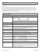
ZERO AND SPAN ADJUSTMENTS
The zero and span adjustments have been factory adjusted to provide zero load voltage when the minimum command
signal is applied and to provide rated output voltage to the load when the maximum command signal is applied. Further
adjustment of these settings should not be required. If it is desired to readjust the zero and span settings the following
procedures should be followed.
Voltage and/or current measurements should be taken with meters that provide true RMS readings due to the chopped
waveforms provided by the SCR controller. Adjust the zero potentiometer with the minimum command signal applied such
that the load voltage is just zero. (Clockwise rotation of both the span and zero potentiometer increase the load voltage)
Adjust the span potentiometer with the maximum command signal applied such that load voltage equals the rated voltage
of the controller. It may be necessary to repeat these steps due to interaction that can occur.
NOTE The 1022 and 1025 controllers have line voltage compensation therefore if the supply voltage is above the nominal
rating the controller will supply the nominal rated voltage to the load.
For example, if a controller rated for 240 volt operation is supplied from a 260 volt supply and the maximum command
signal is applied the controller will supply only 240 volts to the load thereby eliminating the effects of line voltage changes.
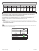
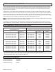
RECOMMENDED SPARE PARTS AND FUSES
RECOMMENDED
REPLACEMENT SCR:
RECOMMENDED FUSES (typical)
(Alternative fuse size is 125% of maximum load current)
MODEL: ASSEMBLY
PART No. *
CCI PART No. BUSSMAN
PART No.
CCI
FUSEKIT **
1022-12-10 or 1025-12-10
1022-12-20 or 1025-12-20
1022-12-30 or 1025-12-30
1022-12-40 or 1025-12-40
1022-12-70 or 1025-12-70
1652-12-10
1652-12-20
1652-12-30
1652-12-40
1652-12-70
42110-0460-315
42110-0460-325
42110-0460-335
42110-0460-350
42110-0460-390
JJS-15
JJS-25
JJS-35
JJS-50
JJS-90
FK\62T15
FK\62T25
FK\62T35
FK\62T50
FK\62T90
1022-24-10 or 1025-24-10
1022-24-20 or 1025-24-20
1022-24-30 or 1025-24-30
1022-24-40 or 1025-24-40
1022-24-70 or 1025-24-70
1652-12-10
1652-12-20
1652-12-30
1652-12-40
1652-12-70
42110-0460-315
42110-0460-325
42110-0460-335
42110-0460-350
42110-0460-390
JJS-15
JJS-25
JJS-35
JJS-50
JJS-90
FK\62T15
FK\62T25
FK\62T35
FK\62T50
FK\62T90
1022-48-10 or 1025-48-10
1022-48-20 or 1025-48-20
1022-48-30 or 1025-48-30
1022-48-40 or 1025-48-40
1022-48-70 or 1025-48-70
1652-48-10
1652-48-20
1652-48-30
1652-48-40
1652-48-70
42110-0460-315
42110-0460-325
42110-0460-335
42110-0460-350
42110-0460-390
JJS-15
JJS-25
JJS-35
JJS-50
JJS-90
FK\62T15
FK\62T25
FK\62T35
FK\62T50
FK\62T90
* The assembly includes the SCR relay, a thermal conductive pad, an MOV and an instruction sheet.
** The fuse kit includes two fuses of appropriate rating for the frame size, and a fuseblock. Control concepts recommends
that fuses be rated at 120 to 125% of maximum load current.
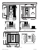
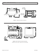
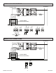
REFERENCE DRAWINGS
Model 1022 Schematic: B1000466
Model 1025 Schematic: B1000324
Transformer Inst. Dwg. AS1401