Instruction Manual ControlIR 915 Another quality product from: 7128 Shady Oak Road • Eden Prairie, MN 55344 (952) 949-9009 Fax (952) 949-9559 www.researchinc.com sales@researchinc.com Rev.
Contents Contents Introduction ..................................................................................................................................... 1 General Description .................................................................................................................... 1 Standard Features ........................................................................................................................ 1 Optional Features ......................................
Theory of Operation .................................................................................................................. 11 Principles of SCR Power Control ......................................................................................... 11 Principles of Phase Angle Control ........................................................................................ 12 Maintenance & Troubleshooting ..........................................................................................
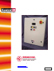
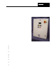
Section 1 Introduction General Description The Model 915 power control system is a complete power control “solution” featuring a number of elements integrated into a single, ready-to-install package. The Model 915 is a single-phase power control system available in a variety of configurations from 120 to 480 volts and rated at 20-, 40-, or 70-amps. These systems are ideally suited for many industrial power control applications and have been specifically optimized for use with Research Inc.
Optional Features The following options are available: Automatic Temperature Control Option The automatic temperature control option allows the power level to be adjusted based on an entered temperature setting for the process. The temperature controller uses PID type control and is pre-wired for a “K” type thermocouple (option code TCT) or a 4/20mA pyrometer signal (option code TCP). Voltmeter Option The true RMS load voltage is displayed with a digital meter.
Section 2 Safety !WARNING! Hazardous voltages are present at the main disconnect switch and load terminals. Setting the setpoint potentiometer or control signal to minimum does NOT eliminate these hazardous voltages. Always remove AC line voltage from the system before making contact with internal assemblies, line or load wiring, or fuses. Also remove AC line voltage from the system before making connections, equipment changes, or resistance measurements.
Section 3 Installation This section describes how to install and wire the Model 915 power control system. The features and options mentioned here are identified in the model number found inside the enclosure. !WARNING! Hazardous voltages are present at the main disconnect switch and load terminals. Setting the setpoint potentiometer or control signal to minimum does NOT eliminate these hazardous voltages.
Wiring Connections The weight of the Model 915 varies slightly with the options installed. The maximum weight of the system is 110 pounds (50 kg). Conduit entry into the system should be made near the right side of the cabinet for power wiring, near the center of the cabinet for load wiring, and near the left side for 120 VAC control wiring. Assure no metal fragments are allowed to fall into the equipment while holes are made for conduit fittings.
Power Wiring Connections Line Connections Referring to the wiring specification in table 3-1, connect the external power lines to the top of the disconnect switch. Load Connections Connect the load to power block PWB 200 load 1 and 2 terminal. Control Connections Refer to Figure 3-2 for connection of the followings items. NOTE: All systems are shipped with a complete set of electrical schematics that depict the “as built” version of the cabinet.
Remote Interlock Switch This feature provides for remote process interlock shutdown of the heater power. This is accomplished by opening the heater power controller contactor. With the interlock open, the heater can not be turned on from the control system front panel. The switch contacts must be open during the heater off condition. If this feature is desired, connect using the following procedure: • Remove the factory installed jumper at TB 100 pins 10 and 11.
• not source current for pyrometer operation. Connect the 4-20mA signal to TB 100 pins 18+ and 19-. “TCT” and “TCP” options: To use the alarm output as an external process alarm. Connect the device for the alarm output to TB 100 pins 20 and 21. If a remote alarm output is not used, the alarm may be connected to the front panel over-temp alarm indicator. Connect TB 100 pin 20 to pin 8 and TB 100 pin 21 to pin 11. The alarm indicator will flash while the temperature controller is in an alarm condition.
Section 4 Operating Instructions Controls and Indicators Figure 4-1 shows the location of the controls and indicators. Main Disconnect Switch The main disconnect switch turns on and off the power control system. Note the following: Before turning on the disconnect switch, check the following: • The load is wired and ready for power to be applied to it. • All safety precautions are observed. Heater ON/OFF Switch The heater ON/OFF switch allows the operator to enable or disable the power going to the load.
Lamp-Out Indicator • Indicator light flashing indicates a lamp out condition. This feature is available only if the lamp out (LL) option is installed. The alarm will remain on as long as the lamp out condition exists. Remote/Local Setpoint Switch The remote/local setpoint switch allows the operator to select the source for the power level setting to the load lamps, or heaters. The selections include: 1. LOCAL: The power level is adjusted using the digial 10-Turn “LOCAL SETPOINT” potentiometer. 2.
Temperature Control Option This section contains temperature controller configuration information for your system. Refer to the model XT19 installation and instruction manual for operating the temperature controller. Setup Summary Table 4-1 displays factory configurations made for your system: Sensor input (TCT option) Sensor input (TCP option) Control Type: AL 1 (alarm 1): Control output: ‘K’ type thermocouple scaled 0-2500 deg. F 4-20mA signal scaled 0-2500 deg.
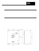
CATHODE ANODE GATE INPUT LINE VOLTAGE OUTPUT LINE VOLTAGE GATING SIGNAL FIRING CIRCUITRY CONTROL SIGNAL Figure 4-2 Conduction of one SCR when turned on at the beginning of a half-cycle. Because an SCR is a type of diode, it can conduct only during every other half-cycle of the applied voltage. Therefore, SCR’s used to control AC power are usually installed in pairs, connected in reverse-parallel, as shown in figure 4-3.
SCR 1 SCR 1 SCR 2 INPUT LINE VOLTAGE SCR 2 OUTPUT LINE VOLTAGE GATING SIGNAL GATING SIGNAL FIRING CIRCUITRY CONTROL SIGNAL Figure 4-4 Conduction of two SCRs connected in reverse parallel when turned on after the beginning of the half-cycles. The average power a phase angle controller delivers to its load is determined by the number of electrical degrees by which the gating signal that turns on the SCRs is delayed past the beginning of the half-cycles.
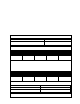
135° PHASE ANGLE LOW POWER OUTPUT 0° 90° 180° 270° 360° 90° 180° 270° 360° 90° PHASE ANGLE MEDIUM POWER OUTPUT 0° 90° 180° 270° 360° 90° 180° 270° 360° 90° 180° 270° 360° 45° PHASE ANGLE HIGH POWER OUTPUT 0° 90° 180° 270° 360° AC PHASE ANGLE AC LINE VOLTAGE OUTPUT VOLTAGE TO LOAD Figure 4-5 Phase angle power control The output voltage of a phase angle controller does not change linearly with respect to the number of degrees the SCR conduction phase angle changes.
output is quite constant, rather than being divided into multiple-cycle periods of on time and off time. In addition, a variety of feedback and output indication (metering) circuits can easily be incorporated into the controller.
Section 5 Maintenance & Troubleshooting Routine Maintenance The following bimonthly routine maintenance is suggested. 1. Remove power connection to the system. Lock out power if possible. Carefully vacuum any dust or dirt collecting within the enclosure. Use caution to not disturb the wiring. Service more often in dusty locations. 2. Clean the outside of the enclosure with glass cleaner and a soft cotton cloth as necessary.
Calibration Generally components of the power control system hold their calibration very well over a long period of time. Usually verification of calibration is all that is necessary. We suggest verification or calibration be performed on a yearly basis. Calibration should be performed by qualified personnel as dangerous voltages are present. Power Controller Refer to the power controller manual for specific calibration instructions.
480 VAC units: 3,750 VDC 240 VAC units: 1,875 VDC 120 VAC units: 0.917 VDC Adjust the EXT 200 span potentiometer if necessary. 7. Verify that the panel voltmeter reads the voltage as set in Step 5 above. If necessary, carefully remove the front cover of the meter and adjust the span potentiometer for a +/1 reading. Temperature Controller Option Refer to the temperature controller manual for calibration instructions.