
User Manual


Page 5 of 21
Wiring Connections
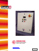
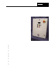
The weight of the Model 915 varies slightly with the options installed. The maximum weight of
the system is 110 pounds (50 kg).
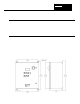
Conduit entry into the system should be made near the right side of the cabinet for power
wiring, near the center of the cabinet for load wiring, and near the left side for 120 VAC control
wiring. Assure no metal fragments are allowed to fall into the equipment while holes are made
for conduit fittings.
We suggest a separate conduit entry should be made for low level DC control wiring if used.
This includes the remote setpoint input or thermocouple wire (temperature control option).
Wire Ratings:
Wire Temperature Rating: 75° C or Higher
Line/Load Wiring Voltage Rating (120/240 VAC) 300 VAC Minimum
Line/Load Wiring Voltage Rating (480 VAC
systems)
600 VAC Minimum
Control Wiring 300 VAC Minimum
Allowable Wire Sizes:
Current
Rating of
System
Line
Connection
Load
Connections
Ground
Connections
Control
Circuit
Connections
20 Amp
40 Amp
70 Amp
14-8 AWG
12-4 AWG
10-1 AWG
14-2 AWG
14-2 AWG
14-2 AWG
14-4 AWG
14-4 AWG
14-4 AWG
22-10 AWG
22-10 AWG
22-10 AWG
NOTE:
Wire temperature and connector ampacity ratings are based on NEC 310-16 using
75°C copper wire derated for 50°C ambient environment.
Recommended Minimum Wire Sizes:
Current
Rating of
System
Line
Connection
Load
Connections
Ground
Connection
Control
Circuit
Connections
20 Amp
40 Amp
70 Amp
12 AWG
8 AWG
4 AWG
12 AWG
8 AWG
4 AWG
12 AWG
10 AWG
8 AWG
16 AWG
16 AWG
16 AWG
Electrical Inputs:
Heater open interlock switch Contacts Rated for 120 VAC at 2.0 A
Cooling flow interlock switch Contacts Rated for 120 VAC at 100mA
Heater Over-temp. thermo switch Contacts Rated for 120 VAC at 100mA
Remote interlock switch Contacts Rated for 120 VAC at 100mA
Table 3-1