S3.
Important Safety Instructions • Never drop or insert objects into any opening. Keep hands away from moving parts. Before beginning any fitness program, see your physician for a complete physical examination. • Never operate the unit when it has been dropped or damaged. Return the equipment to a service center for examination and repair. • Before exercising, make sure that all fasteners and cables are secure and in good working condition.
S3.19 Assembly and Maintenance Guide Table of Contents Important Safety Instructions .................................................................................. 3 Personal Safety During Assembly ............................................................................................................ 3 Obtaining Service ..................................................................................................................................... 3 Table of Contents 1 2 Before You Begin ..
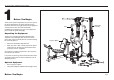
S3.19 Assembly and Maintenance Guide 1 Before You Begin Thank you for purchasing the S3.19. This unit is part of the Precor Strength line of quality strength training machines which let you target specific muscle groups to achieve better muscle tone and overall body conditioning. To maximize your use of the equipment, please study this guide thoroughly. S3.19 Hi/Lo Pulley Assembly Unpacking the Equipment The S3.19 is carefully tested and inspected before shipment.
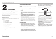
S3.19 Assembly and Maintenance Guide 2 Installation Requirements • Follow these installation requirements when assembling the unit: Preparations CAUTION: To set up this unit, you will need assistance. Do not attempt assembly by yourself. You must review and follow the instructions in this guide. If you do not assemble and use the S3.19 according to the following guidelines, you could void the Precor Limited Warranty. Required Tools • Fill out and mail the warranty registration card.
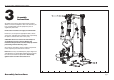
S3.19 Assembly and Maintenance Guide 3 Assembly Instructions Assembly of the S3.19 takes professional installers about 2½ hours to complete. If this is the first time you have assembled this type of equipment, plan on significantly more time. Professional installers are highly recommended! However, if you acquire the appropriate tools, obtain assistance, and follow the assembly steps sequentially, the process will take time, but is fairly easy.
S3.19 Assembly and Maintenance Guide Open the Box Use wire tie cutters to open the boxes. The illustration shows how the S3.19 will look when you have completed its assembly. The callouts identify specific pieces. Lat Bar Important: Most fasteners are fitted to the frame or pulleys, you will need to disassemble the fasteners before proceeding with each step.
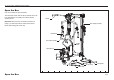
S3.19 Assembly and Maintenance Guide 1. Assemble Main Structure A. Attach the Main Base to the Rear Crossbar using two 4¾-inch hex head bolts four flat washers two locknuts A 2 - 4¾" bolts 4 - washers 2 - locknuts Rear Crossbar B. Install the Rear Upright to the Main Base using two 4¾-inch hex head bolts four flat washers two locknuts Note: Position the uprights so the Shroud mounts face the center of the unit. Main Base C.
S3.19 Assembly and Maintenance Guide D. Disassemble and remove the top pulley and its fasteners on the Main Upright. E. Install the Top Beam on the Rear and Main Uprights. E Align Top Beam with uprights. Note: If necessary, use a rubber mallet to align the mounting holes. F. Secure the Top Beam to the Rear Upright using two 2¼-inch hex head bolts four flat washers two locknuts G.
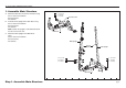
S3.19 Assembly and Maintenance Guide 2. Assemble Leg Extension A. Cut wire ties. B. Attach the Leg Extension to the Main Base using two 2½-inch bolts two spring washers Wrench tighten using a ⁹⁄₁₆ box-end wrench. 2 - 2½” bolts 2 - spring washers B Main Base Leg Extension 1 Step 2.
S3.19 Assembly and Maintenance Guide 3. Install Rollers and Seat Pads A A. Attach the top roller pads using one ½-inch x 3½-inch threaded shaft two ½-inch zinc bolts two zinc flat washers Wrench tighten using the 5mm hex key. B. Attach the two Leg Extension Brackets using four ¾-inch zinc countersunk hex head bolts. 4 - ¾" zinc countersunk bolts C.
S3.19 Assembly and Maintenance Guide G. Attach the Seat Pad to the Seat Stem using four 1-inch zinc buttonhead bolts two zinc flat washers Wrench tighten using a 6mm hex key. Incline Bracket H. Insert the Seat Stem into the Seat Upright Assembly. Pull out the seat adjustment T-handle to insert the stem. Place the Seat Stem at its lowest position. J.
S3.19 Assembly and Maintenance Guide 4. Assemble Weight Stack Important: Obtain adult assistance before installing the Guide Rods and Weights. A C A. Place the Guide Rods into the two outside holes in the Main Base. CAUTION: The lubricant on the Guide Rods can stain clothes. Wear proper attire when working with or lubricating the Guide Rods. B. Place one Guide Rod Spacer and one Weight Cushion on each Guide Rod and allow it to slide down and rest on the Main Base.
S3.19 Assembly and Maintenance Guide D. Orient the hole in the Top Cap Weight with the curve in the weight plates. Place the Top Cap Weight onto the Guide Rods and slide the Selector Stem into the weight stack. D E. Slide the Guide Rod Bracket onto the Guide Rods and secure it to the Upper Frame Crosspiece using two ¾-inch buttonhead bolts two flat washers Wrench tighten.
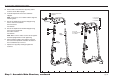
S3.19 Assembly and Maintenance Guide 5. Assemble Press Arm Important: Obtain adult assistance to attach the Press Arm Assembly. A. Attach the Press Arm Assembly, with the label facing out, to the Top Beam using one ¾-inch x 5¼-inch threaded shaft two 1-inch zinc buttonhead bolts two zinc flat washers Wrench tighten. 1 - ¾" threaded shaft 2 - 1" zinc buttonhead bolts 2 - zinc washers A Top Beam Label on Press Arm Assembly Press Arm Assembly Note: Make sure the Press Arm rotates freely.
S3.19 Assembly and Maintenance Guide B. Slide the Handlebars in place on the Press Arm. Handlebars curve inward. Review the illustration for correct handlebar placement. Pull the T-handle up and adjust the handlebars into a secure position. C. Attach the Row Handles using eight ¼ x ½-inch buttonhead screws eight radius washers Press Arm Assembly Note: Make sure the radius washers lie flat against the Row Handle before wrench tightening. D. Wrench tighten the screws using the 5mm hex keys.
S3.19 Assembly and Maintenance Guide 6. Install Hi/Lo Pulley Assembly 2 - 4" bolts 4 - radius washers 2 - locknuts Note: Ask for assistance to move the Hi/Lo Pulley Assembly and align the mounting holes. A. Attach the Hi/Lo Pulley Assembly to the Rear Crossbar using three 1¼-inch hex head bolts three flat washers three spring washers three locknuts Wrench tighten. C D 1 - 2" bolt 1 - washer 1 - locknut Crossbrace B.
S3.19 Assembly and Maintenance Guide 7. Install Lat Pulley Cable Pulley assemblies Note: All pulleys (except the floating pulleys) are installed in the frame assemblies. As you begin each new step, remove the fasteners and pulley. Feed the cable around the pulley as shown, and then replace the fasteners and finger tighten. Wrench tighten all pulley fasteners once you have completed the installation of each cable assembly. A.
S3.19 Assembly and Maintenance Guide E. Feed the cable over the lower 3½-inch pulley located in the Press Arm assembly. Attach the pulley to the Press Arm assembly using one 2-inch zinc hex head bolt two zinc flat washers one zinc locknut F. Feed the cable over the upper 3½-inch pulley located in the Main Upright.
S3.19 Assembly and Maintenance Guide 8. Install Leg Extension Cable A. Remove the hex head bolt from the Gusset which is welded to the Base Frame. Place the end of the Leg Extension Cable 130210 on the bolt as shown. Secure the cable end by reinserting the fasteners: one 2¼-inch hex head bolt one locknut Wrench tighten. B. Disassemble the 3½-inch pulley at the base of the Multiplier Arm.
S3.19 Assembly and Maintenance Guide 9. Install Leg Press Option Cable Connection A. Disassemble the 3½-inch pulley attached to the base frame bracket and feed the threaded end of the Leg Press Option Cable 130211 under the pulley. Reattach the pulley to its bracket using one 2-inch hex head bolt two flat washers one locknut Wrench tighten. B. Attach the threaded end of the cable to the Single Floating Pulley.
S3.19 Assembly and Maintenance Guide 10. Install Mid Pulley Cable and Hi/Lo Pulley Connection A. Disassemble the center pulley on the Main Upright and feed the threaded end of Mid Pulley Cable 130209 through the opening and over the 3½-inch pulley. Attach the pulley to the Main Upright using one 4-inch hex head bolt two shoulder spacers one locknut Wrench tighten. B. Disassemble the Single Floating Pulley attached to the Leg Extension Cable 130210.
S3.19 Assembly and Maintenance Guide C. For proper cable operation, the 3½-inch pulley, located on the Mid-pulley Bracket, must be on the same side as the Hi/Lo Pulley Assembly. If the pulley is not on the correct side, reassemble it. D. Feed the threaded end of the cable over the top of the Mid-pulley Bracket’s 3½-inch pulley. Rest the cable on the floor. MidPulley Bracket Important: Stand between the S3.19 and the Hi/Lo Pulley Assembly and review the cable alignment.
S3.19 Assembly and Maintenance Guide E. Disassemble the Single Floating Pulley attached to the Leg Press Option Cable 130211 and feed the Mid Pulley Cable around the disassembled pulley. Reattach the pulley to the floating pulley housing using one 2-inch zinc hex head bolt two zinc washers one thin zinc locknut Wrench tighten. F. Disassemble the lower portion of the Double Floating Pulley.
S3.19 Assembly and Maintenance Guide J. Feed the threaded end of the cable beneath the 3½-inch pulley at the base of the Hi/Lo Pulley and reattach it using one 2-inch hex head bolt two flat washers one locknut Wrench tighten. K. Cut the wire ties securing the Single Floating Pulley to the Hi/Lo Pulley Assembly. Remove any cable twists or kinks. L. Attach the threaded end of the Mid Pulley Cable to the Single Floating Pulley.
S3.19 Assembly and Maintenance Guide 11. Install Shrouds Note: Read and follow the steps found in Cable Adjustments and Maintenance to lubricate the guide rods and make the appropriate cable adjustments prior to installing the Shrouds. The floating pulleys, guide rods, and selector stem are inaccessible once the acrylic Shrouds are attached.
S3.19 Assembly and Maintenance Guide 12. Attach Accessories A. At the end of the Top Beam, attach the Lat Bar to the Lat Pulley Cable using a spring clip. Note: The two hooks at the end of the Top Beam can be used to store the Lat Bar when it’s not in use. B. The remaining accessories can be attached interchangeably on the Hi-Lo Pulley. Refer to the illustrations. Lat Bar Triceps Strap A Note: To vary your exercise routine, refer to the Wall Chart. C.
S3.19 Assembly and Maintenance Guide 13. Move the Hi/Lo Pulley A. To raise the Hi/Lo Pulley, simply push the Blue Handle up along the track. The Hi/Lo Pulley automatically locks into position. B. To lower the Hi/Lo Pulley, lift the Blue Handle up so it disengages from the track and then slowly lower the Hi/Lo Pulley. Let go of the Blue Handle to lock the Hi/Lo Pulley into position. 1 Step 13.
S3.19 Assembly and Maintenance Guide 14. Apply Weight Decals and Lubricant Weight Label Strip A. Peel the Weight Label off the Weight Label Strip. A B. Peel the backing off the Weight Label to expose the adhesive and place a label on each Weight Plate, starting with the Top Cap Weight. The recommended location of the label is toward the rear of the unit (refer to the illustration). C. Apply one tube of lubricant to each Guide Rod. CAUTION: The lubricant can stain clothes.
S3.19 Assembly and Maintenance Guide 4 Cable Adjustments and Maintenance When the S3.19 is completely assembled, you need to check the cables for proper tension. Obvious signs that cable problems exist include: ✔ Top Cap Weight does not rest squarely on the top weight of the Weight Stack. ✔ Cables rub the inside edges of the pulleys. ✔ Excess slack exists in the cables. ✔ Weight Pin cannot be easily inserted in or removed from each hole in the Weight Stack. ✔ Selector Stem rubs inside the Weight Stack.
S3.19 Assembly and Maintenance Guide 1. Cable Tension If you experience any cable problems, take the following steps to reduce tension on the cables: A. Remove the Weight Pin and set it aside. B. If the Leg Press is attached, place the Support Arm in the upright (non-extended) position. C. Check that the Press Arm rests lightly on the Bumper Pad and is positioned so it causes minimal tension in the cable. If necessary, rotate the Bumper Pad. C D D.
S3.19 Assembly and Maintenance Guide 2. Cable Adjustments You may need to adjust the cables after installation and periodically thereafter. If the cables remain slack after you have followed the steps found in Cable Tension, perform the following: B Threads C Jam Nut A. Remove the Weight Pin and set it aside. B. Loosen the Jam Nut on the Weight Stack threaded end to expose additional threads. Adjust the threaded end until the slack is removed. Top Cap Weight A Top Weight Plate C.
S3.19 Assembly and Maintenance Guide 3. Selector Stem Adjustments If the Selector Stem consistently strikes the inside of the weight stack or it is misaligned with the Weight Stack hole, you can re-center the Selector Stem by taking the following steps: A. To free the Selector Stem, remove the Weight Pin from the Weight Stack. B. Pull up the Selector Stem and place a cover over the opening in the Weight Stack. Rest the Selector Stem on the cover. A C 1 2 3 4 5 6 7 8 9 10 11 C.
S3.19 Assembly and Maintenance Guide 4. Maintenance Guide Rods A Apply one tube of lubricant to each Guide Rod. B. Lubricate the Guide Rods every six months. CAUTION: The lubricant can stain clothes. Wear proper attire when lubricating the Guide Rods. Lubricant Guide Rod Inspection Shrouds Inspect the unit daily. CAUTION: Clean the Shrouds with product specifically labeled as safe for acrylic. Use a clean, nonabrasive cloth and light pressure to avoid scratching the acrylic surface.
Precor Residential Equipment Limited Warranty PLEASE READ THESE WARRANTY TERMS AND CONDITIONS CAREFULLY BEFORE USING YOUR PRECOR INCORPORATED PRODUCT. BY USING THE EQUIPMENT, YOU ARE CONSENTING TO BE BOUND BY THE FOLLOWING WARRANTY TERMS AND CONDITIONS. Limited Warranty. 3. Warranty of all Precor products applies to residential use only and is void when products are used in a nonresidential environment or installed in a country other than where sold. 4.
RET. Precor Incorporated 20031 142nd Avenue NE PO Box 7202 Woodinville, WA 98072-4002 PLACE STAMP HERE Thank You and Welcome to Precor To allow us to serve you better, please take a few moments to complete and return your warranty registration. YOU MAY ALSO REGISTER ONLINE AT www.precor.com/warranty If you have questions or need additional information, contact your local dealer or call Precor Customer Support at 800-347-4404. Fold along dotted line and tape closed before mailing.
Month Day Year Last Name Zip Code Apt./Suite: The serial number is located on the shipping box and on the product.
S3.19 Specifications Length: 77 inches (196 cm) Height: 83 inches (211 cm) Width: 58 inches (147 cm) Width with Leg Press Option: 97 inches (147 cm) Shipping weight: 2 Boxes 418 lb (168.5 kg) Precor Incorporated 20031 142nd Avenue NE P.O. Box 7202 Woodinville, WA USA 98072-4002 1-800-347-4404 Precor is a registered trademark of Precor Incorporated. Specifications subject to change without notice. Copyright 2007 Precor Incorporated. www.precor.