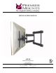
INSTALLATION MANUAL AM3-B Universal Swingout Arm Premier Mounts 3130 E. Miraloma Avenue Anaheim, CA 92806 Phone: (800) 368-9700 Fax: (800) 832-4888 mounts@mounts.com www.mounts.
AM3-B Table of Contents Warning Statements ........................................................................................................................................- 3 Parts List ...........................................................................................................................................................- 4 Installation Tools ...........................................................................................................................................
AM3-B Warning Statements WARNING: PREMIER MOUNTS DOES NOT WARRANT AGAINST DAMAGE CAUSED BY THE USE OF ANY PREMIER MOUNTS PRODUCT FOR PURPOSES OTHER THAN THOSE FOR WHICH IT WAS DESIGNED OR DAMAGE CAUSED BY UNAUTHORIZED ATTACHMENTS OR MODIFICATIONS, AND IS NOT RESPONSIBLE FOR ANY DAMAGES, CLAIMS, DEMANDS, SUITS, ACTIONS OR CAUSES OF ACTION OF WHATEVER KIND RESULTING FROM, ARISING OUT OF OR IN ANY MANNER RELATING TO ANY SUCH USE, ATTACHMENTS OR MODIFICATIONS.
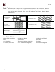
AM3-B Parts List NOTE: This wall mount is shipped with all proper installation hardware and components. Make sure that none of these parts are missing and/or damaged before beginning installation. If there are parts missing and/or damaged, please stop the installation and contact Premier Mounts (800-368-9700).
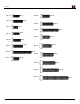
AM3-B M4 x 16 (Qty 8) M6 x 20 (Qty 8) (Qty 8) M4 x 25 (Qty 8) M6 x 30 M5 x 12 (Qty 8) M6 x 45 M5 x 16 (Qty 8) M8 x 20 M5 x 20 (Qty 8) M8 x 25 (Qty 8) (Qty 8) M5 x 50 M8 x 30 (Qty 8) (Qty 8) M8 x 35 M8 x 45 M8 x 70 Installation Manual (Qty 8) (Qty 8) M5 x 25 M6 x 16 (Qty 8) (Qty 8) (Qty 8) (Qty 4) Page - 5 -
AM3-B Nylon spacers and flat washers’ actual size NOTE: The nylon spacers may be stacked to achieve proper spacing.
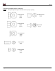
AM3-B Thread Depth Indicator 1. 2. 3. 4. Insert the thread depth indicator (supplied) through the thread inserts found on the back of the flat panel to make sure the inserts measure the same full depth and mark it (Figure 1). Locate the correct diameter screw for the thread insert. Compare your marking to the screws (supplied). If your selected screw is longer than the marking on the thread depth indicator, DO NOT USE this screw. The screw length must not bypass the marking.
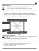
AM3-B Mount Orientation The AM3-B Plasma Mount has the built-in capability of mounting with the swingout arm on either the left or right-hand side. WARNING: WHEN MOUNTING THE AM3-B, THE SIDE THAT THE SWINGOUT ARM IS LOCATED ON MUST HAVE A LAG BOLT MOUNTED ON AT LEAST ONE SIDE (SEE FIGURE 4), TOP AND BOTTOM. 1. 2. To change the mount orientation, choose the desired side that the mount will open to, left or right. Once the side has been determined, attach the mount to the wall.
AM3-B Mount Installation NOTE: Before proceeding with the mount installation, you should already have the mounting holes predrilled. Please use the template (supplied) and follow the instructions. NOTE: For ease of installation, it is recommended that two people perform the installation. WARNING: WHEN MOUNTING THE AM3-B, THE SIDE THAT THE SWINGOUT ARM IS LOCATED ON MUST HAVE A LAG BOLT MOUNTED ON AT LEAST ONE SIDE ( FIGURE 4, PAGE 8), TOP AND BOTTOM. 1. 2. 3.
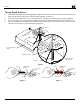
AM3-B Nose Piece Orientation Rotate Nose 180° counter-clockwise Left Hand Orientation Figure 7 Right Hand Orientation Tension Bolts Back Side of Nose Piece Front Side of Nose Piece Figure 8 1. Once the mount has been oriented and mounted to the wall, remove the nose piece by removing the tensions bolts. NOTE: 2. 3. After loosening the tension bolts, be sure that the nose piece is held together tightly before rotating.
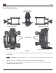
AM3-B Universal Mounting Bracket Assembly 1. 2. 3. 4. 5. Place the universal bracket bar and the universal brackets on a flat surface. Slide the universal brackets onto the universal bracket bar (as shown in Figure 9) with the set screws facing up. At this time, do not tighten the set screws that are located on the universal bracket. Place the display on a soft, flat surface, face-down.
AM3-B Attaching the Display WARNING: ONCE THE UNIVERSAL BRACKET BAR ASSEMBLY HAS BEEN ATTACHED TO THE DISPLAY, IT IS RECOMMENDED THAT TWO PEOPLE MOUNT THE DISPLAY, AS THE UNIT IS HEAVY AND, IF DROPPED, WILL DAMAGE THE MOUNT, THE DISPLAY, AND/OR PERSONNEL. Universal Bracket Universal Bracket Bar Swingout Arm Nose Piece Display Figure 10 1. 2. Figure 12 This is how the units will look when properly fitted together.
AM3-B Securing the Display Once the two units have been secured together, the two (2) M6 x 30mm Phillips Head locking screws must be installed in the noted location (Figure 14) to prevent any movement.
AM3-B Tilt Positioning NOTE: To adjust the display, loosen the tension bolts no more than ½ turn, make the adjustments and then tighten the tension bolts. When tilt positioning is needed to adjust the display, place a hand at the top corner of the display and the other hand at the bottom of the display (Figure 15). To Tilt the Display Gently push both hands inward. This motion will cause the display to tilt forward. To Tilt the Display Back Tilt / Pivot Point Gently push both hands outward.
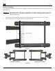
AM3-B Technical Specifications All measurements are in inches(mm).
AM3-B Warranty Limited Lifetime Warranty All Premier Mounts products carry a limited lifetime warranty from ship date against defects in materials and workmanship. Premier Mounts is not liable for improper installation that results in damage to mounts, adapters, display equipment or personal injury. DISCLAIMER OF WARRANTY THE FOREGOING WARRANTY IS IN LIEU OF ALL OTHER WARRANTIES, EXPRESS OR IMPLIED, INCLUDING BUT NOT LIMITED TO THE IMPLIED WARRANTIES OF MERCHANTABILITY AND FITNESS FOR A PARTICULAR PURPOSE.