INSTALLATION MANUAL PSD-BW/PSD-BWL Nesting Cart Series NORTH AMERICA 3130 East Miraloma Avenue Anaheim, CA 92806 USA USA and Canada – Phone: 800-368-9700 Fax: 800-832-4888 EUROPE Swallow House, Shilton Industrial Estate, Shilton, Coventry, England CV79JY Phone: +44 (0) 2476 614700 Fax: +44 (0) 2476 614710 Other Locations – Phone: 001.714.632.7100; Fax: 001.714.632.1044 ©Premier Mounts 2007 9532-003-011-01 AUSTRALIA,NEW ZEALAND, OCEANIA (Distributor) P.O.
PSD-BW/L Table of Contents WARRANTY ....................................................................................................................................................- 2 CONTACT PREMIER MOUNTS ....................................................................................................................- 2 WARNING STATEMENTS .............................................................................................................................- 3 PARTS LIST .....................
PSD-BW/L Warning Statements WARNING: WARNING: PREMIER MOUNTS DOES NOT WARRANT AGAINST DAMAGE CAUSED BY THE USE OF ANY PREMIER MOUNTS PRODUCT FOR PURPOSES OTHER THAN THOSE FOR WHICH IT WAS DESIGNED OR DAMAGE CAUSED BY UNAUTHORIZED ATTACHMENTS OR MODIFICATIONS, AND IS NOT RESPONSIBLE FOR ANY DAMAGES, CLAIMS, DEMANDS, SUITS, ACTIONS OR CAUSES OF ACTION OF WHATEVER KIND RESULTING FROM, ARISING OUT OF OR IN ANY MANNER RELATING TO ANY SUCH USE, ATTACHMENTS OR MODIFICATIONS.
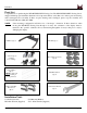
PSD-BW/L Parts List Congratulations on purchasing the PSD-BW/PSD-BWL Nesting Cart. The PSD-BW/PSD-BWL Nesting Cart is shipped with all proper installation hardware and components. Please verify that none of these parts are missing and/or damaged before assembly. If there are parts missing and/or damaged, please stop the assembly and contact Premier Mounts (800) 368-7000. NOTE: Some mounting configurations will allow for a “landscape” orientation.
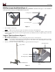
PSD-BW/L BW Base Castor Installation (Figure 1) Unpack the PSD-BW/L Nesting Cart and review any WARNING statements that apply to the installation. Select the desired location for the PSD-BW/L Nesting Cart. Locking Castor Non-Locking Castor Figure 1 1. Place the BW/L on a flat surface. NOTE: 2. Make sure the locking castors (Qty 2) are attached to the rear legs of the Nesting Cart. Insert each castor into the threaded mounting point located on the underside of the BW/L base (Figure 1).
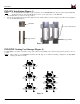
PSD-BW/L PSD-SPA Installation (Figure 3) NOTE: 1. 2. Use of the PSD-SPA will depend on the mount that is used. All PSM/CTM Series mounts require using the PSD-SPA. The Revolution Series, USA and UFA Mounts, however, do not require the use of the PSD-SPA. Slide the PSD-SPA over and down the support tubes. Once the desired height has been determined, tighten the four (4) M8 x 10mm set screws, using the 5/32” Allen wrench (supplied) to secure the PSD-SPA (Figure 3).
PSD-BW/L Optional Mounting Configurations CTM-Series Revolution Series USA/UFA Series Page 7 Installation Instructions
PSD-BW/L Technical Specifications All measurements are in inches (mm).
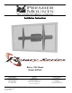
Installation Instructions Rotary Tilt Mount Model: RTM-L NORTH AMERICA 3130 East Miraloma Avenue Anaheim, CA 92806 USA USA and Canada Phone: 800-368-9700 Fax: 800-832-4888 EUROPE Swallow House, Shilton Industrial Estate, Shilton, Coventry, England CV79JY Phone: +44 (0) 2476 614700 Fax: +44 (0) 2476 614710 Other Locations - Phone: (001)-714-632-7100; Fax: (001)-714-632-1044 ©Premier Mounts 2007 9531-009-011-00 AUSTRALIA, NEW ZEALAND, OCEANIA (Distributor) P.O.
RTM-L TABLE OF CONTENTS Warranty Contact Premier Mounts Warning Statements Parts List Installation Tools Thread Depth Indicator Mount Installation Universal Mounting Bracket Installation Display Orientation Securing the Display Tilt Positioning Optional Configurations Technical Specifications Addendum 2 2 3 4 4 7 8 9 11 11 12 12 12 13 PREMIER MOUNTS LIMITED LIFETIME WARRANTY What and Who is Covered by this Limited Warranty and for How Long Premier Mounts warrants this product to be free from defects in m
RTM-L Warning Statements WARNING: PREMIER MOUNTS DOES NOT WARRANT AGAINST DAMAGE CAUSED BY THE USE OF ANY PREMIER MOUNTS PRODUCT FOR PURPOSES OTHER THAN THOSE FOR WHICH IT WAS DESIGNED OR DAMAGE CAUSED BY UNAUTHORIZED ATTACHMENTS OR MODIFICATIONS, AND IS NOT RESPONSIBLE FOR ANY DAMAGES, CLAIMS, DEMANDS, SUITS, ACTIONS OR CAUSES OF ACTION OF WHATEVER KIND RESULTING FROM, ARISING OUT OF OR IN ANY MANNER RELATING TO ANY SUCH USE, ATTACHMENTS OR MODIFICATIONS.
RTM-L Parts List NOTE: This mount is shipped with all installation hardware and components. Make sure that none of these parts are missing and/ or damaged before beginning installation. If there are parts missing and/or damaged, please stop and contact Premier Mounts (800) 368-9700.
RTM-L Parts List (Cont.
RTM-L Parts List (Cont.) Nylon spacers and flat washers' actual size The nylon spacers may be stacked to achieve proper spacing.
RTM-L Thread Depth Indicator 1. 2. 3. 4. Insert the thread depth indicator (supplied) through the thread inserts found on the back of the flat panel to make sure the inserts measure the same full depth and mark it (Figure 1). Locate the correct diameter screw for the thread insert. Compare your marking to the screws (supplied). The screw length must not bypass the marking. Select another screw size (Figure 2 and 3), until you find one that comes closest to your mark without going past.
RTM-L Mount Installation NOTE: NOTE: The installation instructions that are contained in this manual refer only to the RTM-L. The installation instructions for the various bases that are used with the RTM-L will be included with those products. Prior to installing the RTM-L, the mounting configuration must already be assembled (base, support poles, etc.). Mounting Block Set Screws Cradle Support Poles 1. Slide the mounting block over and down the support poles. Page 8 2.
RTM-L Universal Mounting Bracket Assembly 1. Place the universal bracket bar and the universal brackets on a flat surface. 2. Slide the universal brackets onto the universal bracket bar (as shown below) with the set screws facing up. At this time, do not tighten the set screws that are located on the universal bracket. 3. Place the display on a soft, flat surface, face-down.
RTM-L 3. Lower the universal bracket bar and display into the cradle (as to the left). Nylon Sleeve NOTE: The circular portion of the universal bracket bar must rest inside the nylon sleeve. If seated improperly, the operation of the RTM-L will be hindered and the nylon sleeve will become damaged. Knurl Knob Mounting Points (a knurl knob may be placed in either mounting hole) 4. Insert an M6 knurl knob into the knurl knob mounting point and tighten. Locking Screws 5.
RTM-L Display Orientation The RTM-L will allow the user to adjust the display a full 360°. WARNING: BEFORE ROTATING THE RTM-L, MAKE SURE THAT THE M6 KNURL KNOB IS SECURELY FASTENED TO THE RTM-L. ALSO, PLEASE MAKE SURE YOU ALLOW ENOUGH CABLE AND WIRE CLEARANCE FOR FULL ROTATION. 1. To adjust the RTM-L, rotate the display either clockwise or counter-clockwise. 2. Tighten the two Phillips head locking screws (see Step 5, Page 10).
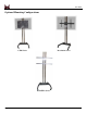
RTM-L Optional Configurations PSD-TS PSD-BW PSD-EB Technical Specifications All measurements are in inches (mm).
RTM-L Addendum RTM-L ADDENDUM: The RTM-L is shipped with the hand crank in the storage position. The hand crank must be removed in order for the RTM-L to be adjusted. After the adjustments have been made, return the hand crank to the storage position. If the hand crank is not returned to the storage position, it may cause damage to the unit or other equipment. Please return the hand crank to the storage position after operation.
INSTALLATION MANUAL PSD-SHB Black Shelf Step 1 Open the box and remove all components. Step 2 Slide the shelf over the poles, select the desired height and lock the height by tightening the four (4) Allen head screws using the hex key. 1 2 Phone: 1300 666 099 www.idt.com.