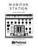
MONITOR STATION Studio Control Center User’s Manual v1.0 © 2007, PreSonus Audio Electronics, Inc. All Rights Reserved.
PRESONUS LIMITED WARRANTY PreSonus Audio Electronics Inc. warrants this product to be free of defects in material and workmanship for a period of one year from the date of original retail purchase. This warranty is enforceable only by the original retail purchaser. To be protected by this warranty, the purchaser must complete and return the enclosed warranty card within 14 days of purchase.
TABLE OF CONTENTS 1 OVERVIEW 1.1 Introduction ........................................................................................................................................... 2 1.2 Features ................................................................................................................................................ 3 1.3 What is in the Box .................................................................................................................................
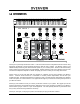
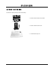
OVERVIEW 1.1 INTRODUCTION Thank you for purchasing the Monitor Station. PreSonus Audio Electronics designed the Monitor Station using high-grade components to ensure optimum performance that will last a lifetime. The Monitor Station is the ultimate desktop monitoring and communications system for your recording studio.
OVERVIEW 1.2 FEATURES The Monitor Station is the ultimate studio control center complete with everything needed for real-world, modern studio applications. The Monitor Station comes complete with a built-in talkback mic, three source inputs, three speaker outputs, four headphone amplifiers and control over the routing and level of every element connected to the Monitor Station – effectively giving you complete control over your entire studio environment.
OVERVIEW 1.
OPERATION 2.1 QUICK START The Monitor Station Quick Start guide was written to help get your Monitor Station connected to your system as quickly as possible. The following step-by-step instructions are based on a common studio environment. Your actual setup may change based on your needs and applications. 2.1.1 Connect the power Before connecting any power supply to the Monitor Station, ensure the power supply meets the input voltage requirements of the region or country you are using it in.
OPERATION 2.1.3 Calibrate the LED meter By default, the Monitor Station’s LED meters are calibrated so the red 0 dBVU LED illuminates when the selected source signals reach +10 dBu. This can be changed so that 0 dBVU references +4, +10 or +18 dBu. +4 dBu 0 dBVU should reference +4 dBu if any of your monitoring devices have a maximum input of +4 dBu or if none of your input devices have a maximum (or nominal) output level greater than +4 dBu.
OPERATION 2.1.5 Connect the speakers 1) “Zero” the Main level knob by turning it fully counterclockwise. 2) Connect your primary monitoring system (such as a pair of nearfield reference monitors) to the Left and Right outputs of Speaker A. 3) [Optional]: Connect your secondary monitoring system (such as a pair of reference monitors of a different make or model) to the Left and Right outputs of Speaker B.
OPERATION Maximum Loudness Reference This method references a 0 dBVU meter reading to the loudest level you or your studio can handle or desire. This is the least technical, most subjective method and is good for environments where there is such a thing as “too loud” (i.e. an apartment, school, OSHA-regulated venue, etc.) or when a certain level of “louder” needs to be attainable (i.e. for entertaining guests at parties, clubs, live venues, etc.).
OPERATION 85 dB SPL “Standard” Reference This method references a specific “standard” meter reading to a certain acoustic level. This method is the most technical, least subjective method and is good for studios where a specific type of audio is produced or where an industry standard audio level exists (such as for film or broadcast). One of the most common calibration standards (and the one presented here) is -20 dBFS referenced to 85 dB SPL.
OPERATION 2.1.7 Calibrate the talkback microphone 1) “Zero” the Main, Talkback, Cue, Phones and Dim knobs by turning them fully counterclockwise. 2) [Optional]: Connect a dynamic microphone to the external mic XLR input connection. 3) Connect headphones to any one of the headphones connections and select ‘CUE’ as its source. 4) Play audio common to your studio’s productions (such as a commercial CD or existing project) and set that audio source as the only input to the Cue bus (section 3.1.4).
OPERATION 2.2 SAMPLE HOOK UP DIAGRAM With the Monitor Station, you can simultaneously record and play back up to 10 channels. Since it is loaded with eight preamplifiers, you can plug in eight microphones to the Monitor Station along with S/PDIF digital input to record a full band. This makes recording extremely easy. All you need are a few microphones, some cables to connect them, a musician (or two or three or more) and the creative energy to bring it all together. This is a typical rock band setup.
OPERATION 2.3 ADVANCED MODES To enhance the Monitor Station’s functionality, the behavior of the input LED meter and Speaker Select, Main Source and Cue Source buttons can be changed to best suit your studio environment. Enter the following modes by pressing and holding the specified buttons while powering on the Monitor Station. Only one mode can be set at a time. The Monitor Station remains in the selected modes until another is selected. 2.3.
OPERATION 2.3.3 Input LED Meter Modes • +4 dBu References 0 dBVU to +4 dBu. 0 dBVU should reference +4 dBu if any of your monitoring devices have a maximum input of +4 dBu or if none of your input devices have a maximum (or nominal) output level greater than +4 dBu. • +10 dBu The default LED meter reference level: 0 dBVU = +10 dBu.
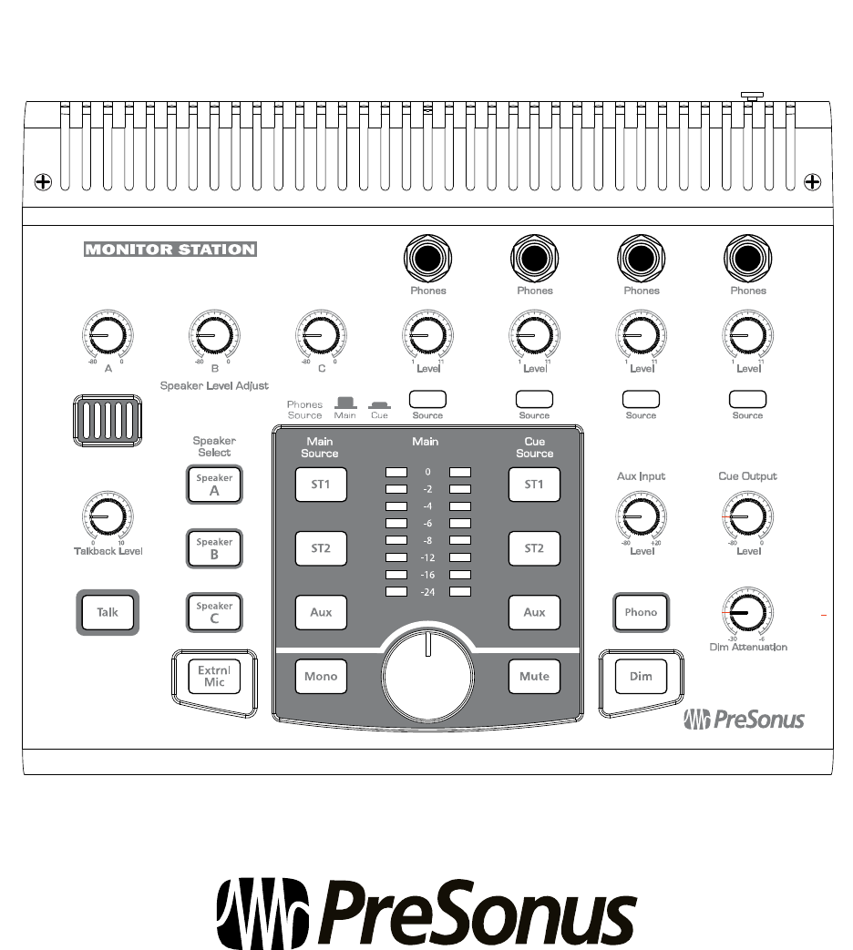
CONTRO OLS & CO ONNE ECTIO ON 3.1 FR RONT PAN NEL LAYO OUT 3.1.1 Talkback • m T built-in taalkback micropphone is an electret condenser microphonne and The Talkback microphone. is positioneed just above the Talkback Level L knob. • Talkback Level. L Adjustss the gain levell of the talkbacck microphonee preamplifier +15 to +55 dB. d • Talk. Eng gages and diseengages the taalkback micropphone preampplifier. The taalkback microophone routes to the t Cue bus only.
CONTRO OLS & CO ONNE ECTIO ON 3.1.2 Headphon nes • Phones. Connects headphones to the Monitor M Statioon’s four headpphone amplifieers. • Level. Adjusts the outpuut level of the associated a heaadphone ampliffier. • Source. Changes the inpput source of the associatedd headphone amplifier. a A headphone h amplifier will use thee selected Main source wheen the associatted Phones Soource button is in the up poosition and the Cuee Source whenn the associated Phones Source button is in the down position.
CONTROLS & CONNECTION 3.1.4 Source Control • Main Source. Sets the Main bus’ input sources. The Main bus is the source for the Speaker outputs, Main L/R outputs and any headphone amplifiers whose source is set to ‘Main’. By default, the Main and Cue Source buttons are in Input Sum mode and can all be selected simultaneously. For more information on changing the Source Control mode, please refer to section 2.3 of this User’s Manual. • Cue Source. Sets the Cue bus’ input sources.
CONTRO OLS & CO ONNE ECTIO ON 3.1.5 Speaker Control C • evel Adjust. Fine F tunes the output level off each stereo output o pair. The T optimum leevel of Speaker Le these knobs fully clockw wise (Unity Gaain). Ideally, these should only be adjussted below Unnity to attenuate your y speaker outputs during the calibrationn process. • Speaker Select. Activaates the Speaker Outputs A, A B and C.
CONTRO OLS & CO ONNE ECTIO ON 3.1.6 Main Leve el Control • Main Level. Adjusts the output level of o the active Sppeaker sets (A A, B and C). • Mono. Co onverts the steereo Main buus source to a mono signall (does not afffect the Main L/R outputs). The T mono sum mming bus is only o active when the Mono button b is lit. The mono sum mming bus is helpfful when mixinng in stereo to determine if your y mix has any a phasing isssues between the left and right channels.
CONTROLS & CONNECTION 3.2 BACK PANEL LAYOUT 3.2.1 Inputs • Talkback Mic. Connects a dynamic microphone to the built-in talkback microphone preamplifier. • ST1. Connects a stereo source to the Stereo 1 input bus. • ST2. Connects a stereo source to the Stereo 2 input bus. • Aux / Phono. Connects an unbalanced stereo source to the Auxiliary input bus.
CONTROLS & CONNECTION 3.2.2 Outputs • Main. Connects the Main bus to a stereo device. The Main L/R outputs derive their signal directly from the Main Source selection and are not affected by any of the Main bus level controls. • Cue. Connects the Cue bus to a stereo device. The Cue L/R outputs derive their signal directly from the Cue Source selection and are only affected by the Cue Input Level control knob. • A. Connects the Main-Speaker A bus to a stereo device.
TECHNICAL INFORMATION 4.1 FREQUENTLY ASKED QUESTIONS Why can’t I hear the talkback microphone? • • • • Remember, only headphones with a Phones Source of ‘CUE’ can hear the talkback microphone. Connect and/or calibrate your talkback microphone according to section 2.1.7. Verify your external mic does not require phantom power. If you are not using an external microphone, disconnect anything connected to the XLR input.
TECHNICAL INFORMATION 4.2 TROUBLESHOOTING Please note that many technical issues can arise when connecting different components in a studio environment. PreSonus can only provide support for issues directly related to the Monitor Station Studio Control Center. It may be necessary to contact the manufacturer(s) of your other studio equipment to obtain additional technical support. PreSonus does not provide support for issues in regards to non-PreSonus hardware or software. Please check our website, www.
TECHNICAL INFORMATION 4.3 SPECIFICATIONS Audio Inputs Talkback Microphone Gain Range ..................................................................................................................... +15 to +55 dB Internal Microphone Type ...................................................................................................................... electret condenser Sensitivity ......................................................................................................................
TECHNICAL INFORMATION Audio Outputs Type .................................................................................................................... ¼” TRS Active Balanced Output Impedance (Balanced) ............................................................................................................ 51 Ω THD+N (unwtd, 1 kHz @ 0 dBu, Unity Gain) ............................................................................... <0.003% Frequency Response (±0.5 dB) ...............................
TECHNICAL INFORMATION 4.