JAZZY SELECT SERIES Jazzy Select Jazzy Select 6 Jazzy Select 6 Ultra Including Models: Jazzy Select, Jazzy Select 6, and Jazzy Select 6 Ultra 1-800-800-8586 (US) 1-888-570-1113 (Canada)
SAFETY GUIDELINES WARNING! An authorized Pride Provider or a qualified technician must perform the initial setup of this power chair and must perform all of the procedures in this manual. The symbols below are used throughout this owner's manual and on the power chair to identify warnings and important information. It is very important for you to read them and understand them completely. WARNING! Indicates a potentially hazardous condition/situation.
CONTENTS I. INTRODUCTION ................................................................................................................................... 4 II. SAFETY .................................................................................................................................................... 5 III. YOUR POWER CHAIR ......................................................................................................... 17 IV. ASSEMBLY ........................................
I. INTRODUCTION SAFETY WELCOME to Pride Mobility Products Corporation (Pride). The power chair you have purchased combines state-ofthe-art components with safety, comfort, and styling in mind. We are confident that these design features will provide you with the conveniences you expect during your daily activities. Once you understand how to safely operate and care for your power chair, it should give you years of trouble-free operation and service.
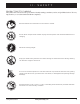
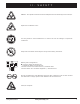
II. SAFETY PRODUCT SAFETY SYMBOLS The symbols below are used on the power chair to identify warnings, mandatory actions, and prohibited actions. It is very important for you to read and understand them completely. Read and follow the information in the owner’s manual. Do not allow unsupervised children to play near the power chair while the batteries are charging. Maximum seating weight. Keep your hands away from the tires when driving.
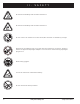
II. SAFETY Do not lift the mobility vehicle while seated in it. Do not lift the mobility vehicle while seated in it. Do not connect an extension cord to the AC/DC converter or the battery charger. Removal of grounding prong can create electrical hazard. If necessary, properly install an approved 3-pronged adapter to an electrical outlet having 2-pronged plug access. Wear safety goggles. Corrosive chemicals contained in battery. Do not remove the anti-tip wheels. 6 www.pridemobility.
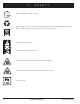
II. SAFETY EMI-RFI - This product has been tested and passed at an immunity level of 20 V/m. Explosive conditions exist! Use only AGM or Gel-Cell batteries to reduce the risk of leakage or explosive conditions. Keep tools and other metal objects away from battery terminals.
II. SAFETY Battery charger for indoor use only. Disposal and recycling - Contact your authorized Pride Provider for information on proper disposal and recycling of your Pride product and its packaging. Locked and in drive mode. Unlocked and in freewheel mode. Do not place power chair in freewheel mode on a decline. Do not place power chair in freewheel mode on an incline. Contains Lead. 8 www.pridemobility.
II. SAFETY GENERAL GUIDELINES MANDATORY! Do not operate your new power chair for the first time without completely reading and understanding this owner’s manual. Your power chair is a state-of-the-art life-enhancement device designed to increase mobility. Pride provides an extensive variety of products to best fit the individual needs of the power chair user.
II. SAFETY Weight Limitations Your power chair is rated for a maximum weight capacity. Please refer to the specifications table for this limit. MANDATORY! Stay within the specified weight capacity of your power chair. Exceeding the weight capacity voids your warranty. Pride will not be held responsible for injuries and/or property damage resulting from failure to observe weight limitations. WARNING! Do not carry passengers on your power chair.
II. SAFETY WARNING! Never travel down an incline backward. Doing so may cause the power chair to tip. Always exercise extreme caution when negotiating an incline. WARNING! Even though your power chair is capable of climbing slopes greater than those illustrated in figure 1, do not, under any circumstances, exceed the incline guidelines or any other specifications presented in this manual. Doing so could cause instability in your power chair.
II. SAFETY Public Streets and Roadways WARNING! You should not operate your power chair on public streets and roadways. Be aware that it may be difficult for traffic to see you when you are seated on your power chair. Obey all local pedestrian traffic rules. Wait until your path is clear of traffic, and then proceed with extreme caution.
II. SAFETY Stairs and Escalators Power chairs are not designed to travel up or down stairs or escalators. Always use an elevator. WARNING! Never use your power chair to negotiate steps or escalators. Doors ! Determine if the door opens toward or away from you. ! Drive your power chair gently and slowly forward to push the door open. Or drive your power chair gently and slowly backward to pull the door open.
II. SAFETY Batteries In addition to following the warnings below, be sure to comply with all other battery handling information. For more information about your power chair’s batteries, see VI. “Batteries and Charging.” MANDATORY! Battery posts, terminals, and related accessories contain lead and lead compounds. Wear goggles and gloves when handling batteries and wash hands after handling. WARNING! Power chair batteries are heavy. See specifications table.
II. SAFETY Transfers Transferring onto and off of your power chair requires a good sense of balance. Always have an attendant or healthcare professional present while learning to properly transfer yourself. To eliminate the possibility of injury, Pride recommends that you or a trained attendant perform the following tasks before attempting a transfer: ! Turn off the power to the controller. ! Ensure your power chair is not in freewheel mode. See III. “Your Power Chair.
II. SAFETY Alcohol/Smoking The power chair user must exercise care and common sense when operating his/her power chair. This includes awareness of safety issues while under the influence of alcohol or while smoking. WARNING! Do not operate your power chair while you are under the influence of alcohol, as this may impair your ability to operate your power chair in a safe manner.
III. YOUR POWER CHAIR THE JAZZY SELECT SERIES POWER CHAIR The Jazzy Select Series Power Chair has two main assemblies: the seat assembly and the power base assembly. See figure 5. Typically, the seat assembly includes the armrests, seatback, and seat base. The power base assembly includes two motor/ brake assemblies, two drive wheels, two batteries, and wiring harnesses.
III. YOUR POWER CHAIR XLR OFF-BOARD CHARGER HARNESS CONNECTOR REAR SHROUD SEAT POST FRONT COVER MAIN CIRCUIT BREAKER CASTER WHEEL CONTROLLER HARNESS ANTI-TIP WHEELS Figure 6. The Jazzy Select Power Base XLR OFF-BOARD CHARGER HARNESS CONNECTOR REAR SHROUD SEAT POST MAIN CIRCUIT BREAKER REAR CASTER WHEEL CONTROLLER HARNESS FRONT COVER FRONT CASTER WHEELS Figure 7. The Jazzy Select 6 Power Base 18 www.pridemobility.
III. YOUR POWER CHAIR POWER SEAT ACTUATOR REAR SHROUD MAIN CIRCUIT BREAKER CONTROLLER HARNESS REAR CASTER WHEEL FRONT COVER FRONT CASTER WHEELS Figure 8. The Jazzy Select 6 Ultra Power Base Jazzy Select Series www.pridemobility.
III. YOUR POWER CHAIR Electrical Components The electrical components are located either on or inside the power base. The main circuit breaker is located on the front of the power base. The power module is located under the front cover. See figures 6, 7, and 8. Main Circuit Breaker: The main circuit breaker is a safety feature built into your power chair. When the batteries and the motors are heavily strained (e.g.
III. YOUR POWER CHAIR CONTROLLER CONNECTOR MOTOR CONNECTORS BATTERY CONNECTORS MAIN CIRCUIT BREAKER BATTERY CONNECTORS Figure 10. Jazzy Select 6 Ultra Electrical Components Jazzy Select Series www.pridemobility.
III. YOUR POWER CHAIR Manual Freewheel Levers Your power chair has a manual freewheel lever on each motor. Manual freewheel levers enable you to disengage the drive motors from the gearboxes and maneuver the chair manually. WARNING! Do not use the power chair while the drive motors are disengaged! Do not disengage the drive motors when the power chair is on an incline or decline, as the unit could roll on its own. Only engage the freewheel mode when on a level surface.
I V. ASSEMBLY INITIAL ASSEMBLY Your power chair may require some assembly either before initial use or after transportation. NOTE: Any nylon insert lock nut removed during the disassembly or adjustment of the power chair must be replaced with a new nylon insert lock nut. Nylon insert lock nuts should not be reused as it may cause damage to the nylon insert, resulting in a less secure fit. Replacement nylon insert lock nuts are available at local hardware stores or through your authorized Pride Provider.
I V. ASSEMBLY Quick Release Fasteners: The seat is secured to the seat post with a quick release fastener. The quick release fastener consists of a bolt, a lever, and a nut. See figure 14. The lever has a cam on the end that allows it to clamp into place. The quick release fastener has two states: clamped and unclamped. When the lever is open, the quick release fastener is unclamped. When the lever is closed, the quick release fastener is clamped. To clamp the quick release fastener: 1.
I V. ASSEMBLY NOTE: It is important that the armrest be lifted straight up prior to securing the controller harness with wire-ties. M A N DATO RY ! P r eve n t c o n t r o l l e r harness damage! Avoid routing the controller harness on the outside of the armrest pad. Route the harness under the armrest or toward the inside of the armrest pad.
V. COMFORT ADJUSTMENTS COMFORT ADJUSTMENTS After becoming familiar with your power chair’s operation, you may find the need to make some adjustments to increase your comfort, such as seat height, armrest angle, foot platform height and angle, and controller position. Refer to the following information before making comfort adjustments. NOTE: If your power chair is equipped with an optional seating system, please refer to the information provided in separate manuals.
V. COMFORT ADJUSTMENTS Seat Height Adjustment (Select 6 Ultra Only) Your power chair is equipped with a power elevating seat. You can change the seat height through the controller. To change the seat height: 1. Push the on/off key to power on the chair and the controller. See figure 20. 2. Push the desired actuator key to select actuator mode. See figure 20. 3. Push the joystick forward to raise the seat to the desired position. 4. Pull the joystick backward to lower the seat to the desired position. 5.
V. COMFORT Manual Recline Seatback Adjustment If your power chair is equipped with a manual recline seatback, you can adjust the seatback angle with the seatback release lever. The lever is located on the right side of the seat base. See figure 21. To adjust the recline angle: 1. Pull up on the seatback release lever. 2. Lean forward or backwards to the desired position. 3. Release the lever.
V. COMFORT ADJUSTMENTS Armrest Height Adjustment To change the armrest height: 1. Loosen the setscrews on the armrest. See figure 21. 2. Raise or lower the armrest to the desired height. 3. Tighten the setscrews to secure the armrest. SETSCREW Controller Position You can move the controller in toward or out away from the armrest, or change the position of the controller for either lefthand or right-hand use.
V. COMFORT ADJUSTMENTS Foot Platform Height Adjustment The foot platform height is easily adjusted to different heights in 0.5-in. (1.27 cm) increments. To raise or lower the foot platform: 1. Remove the fasteners from the foot platform bracket. See figure 23 or 24. 2. Raise or lower the foot platform to the desired height. 3. Reinstall the fasteners into the foot platform bracket and tighten. Foot Platform Depth Adjustment To adjust the foot platform depth: 1.
V. COMFORT ADJUSTMENTS Swing-away Footrests Swing-away Footrests (SFRs) enable you to rotate the footrests to the side before you transfer onto or off or your power chair. See figure 25. SFR RELEASE LEVER To rotate the SFRs: 1. Push in the release lever. 2. Rotate the SFRs. FOOTREST EXTENSION To adjust the SFR length: 1. Remove the adjustment screws from the footrest extension. 2. Slide the footrest up or down to the desired length. 3. Reinstall the two adjustment screws.
V. COMFORT ADJUSTMENTS Anti-Tip Wheels (Select Only) The anti-tip wheels are designed to give your power chair increased stability on rough surfaces. The anti-tip wheels are preset at the factory for smooth surfaces or indoor use only. If you plan on using your power chair on rough surfaces, it may be necessary to adjust the anti-tip wheels to better suit your needs. The anti-tip wheels may need adjustment if the following occurs: ! When coming to a stop, your power chair tips forward excessively.
VI. BATTERIES AND CHARGING BATTERIES AND CHARGING Your power chair uses two long-lasting, 12-volt, deep-cycle batteries. These batteries are sealed and maintenance free. Since they are sealed, there is no need to check the electrolyte (fluid) level. Deep-cycle batteries are designed to handle a longer and deeper discharge. Though they are similar in appearance to automotive batteries, they are not interchangeable.
VI. BATTERIES AND CHARGING To charge the batteries using the off-board charger: 1. Position the front of your power chair next to a standard electrical outlet. 2. Be certain the controller power is turned off and the freewheel levers are in the engaged position. See III. “Your Power Chair.” 3. Plug the off-board charger into the off-board charger/ programming socket on the controller. See figure 28. 4. Plug the off-board charger into the electrical outlet.
VI. BATTERIES AND CHARGING How often must I charge the batteries? Many factors come into play when deciding how often to charge the batteries. You may use your power chair all day on a daily basis or you may not use it for weeks at a time. ! Daily Use If you use your power chair on a daily basis, charge the batteries as soon as you are finished using your power chair. Your power chair will be ready each morning to give you a full day’s service.
VI. BATTERIES AND CHARGING How can I ensure maximum battery life? A fully charged deep-cycle battery will provide reliable performance and extended battery life. Keep your power chair’s batteries fully charged whenever possible. Batteries that are regularly and deeply discharged, infrequently charged, or stored without a full charge may be permanently damaged, causing unreliable power chair operation and limited battery life.
VII. CARE AND MAINTENANCE CARE AND MAINTENANCE Your Jazzy is a sophisticated power chair. Like any motorized vehicle, it requires routine maintenance checks. You can perform some of these checks, but others require assistance from your authorized Pride Provider. Preventive maintenance is very important. If you follow the maintenance checks in this section as scheduled, you can help ensure that your power chair gives you years of trouble-free operation.
VII. CARE AND MAINTENANCE ! All wheel bearings are prelubricated and sealed. They require no subsequent lubrication. ! The body shroud has been sprayed with a clear sealant coating. You can apply a light coat of car wax to help it retain its high-gloss appearance. ! Check all electrical connections. Make sure they are tight and are not corroded. Batteries must sit flat within the battery boxes and battery well frame with the battery terminals facing inward toward each other.
VII. CARE AND MAINTENANCE Storage Your power chair should be stored in a dry place, free from temperature extremes. When storing, disconnect the batteries from the power chair. See VI. “Batteries and Charging.” WARNING! If you fail to store the unit properly, the frame can rust and the electronics can be damaged.
VII. MOTOR KEY CARE AND MAINTENANCE DRIVE WHEEL TUBE ACORN NUTS DRIVE WHEEL NUT HUB CAP AXLE WHEEL HUB RIM HALF RIM HALF TIRE WARNING! Completely deflate the tire before attempting repair. DRIVE WHEEL WASHER Figure 29. Jazzy Select Series Drive Wheel Removal Figure 30. Jazzy Select Series Drive Wheel Disassembled Follow these easy steps for a quick and safe repair for both pneumatic and solid tires: 1. Turn off the power to the controller. 2. Make sure that the power chair is in drive mode.
VII. CARE AND MAINTENANCE CORRECT CONNECTION INCORRECT CONNECTION REAR SHROUD FRONT COVER YELLOW THUMBSCREWS REAR BATTERY FRONT BATTERY SIDE COVER Figure 31. Battery Installation (Seat Removed for Clarity - Select 6 Shown) Jazzy Select Series www.pridemobility.
VII. CARE AND MAINTENANCE WARNING! Do not mix old and new batteries. Always replace both batteries at the same time. To replace the batteries: 1. Turn off power to the controller. 2. Make sure that the power chair is in drive mode. See figure 11. 3. Remove the rear shroud. See figure 31. 4. Loosen the yellow thumbscrews and remove the side cover. 5. Disconnect the rear battery harness from the power base. See figure 31. 6. Slide the rear battery out of the power base. 7.
VII. CARE AND MAINTENANCE Corrective Maintenance If the battery condition meter does not light up when you turn on the power: ! Check the harness connections. Make sure they are tight. ! Check the circuit breaker. Reset it if necessary. ! Check the battery connections. If the above conditions prove normal, you can load test the batteries with a battery load tester. These testers are available at automotive parts stores.
VIII.
VIII. WARRANTY SERVICE CHECKS AND WARRANTY SERVICE Warranty service must be performed by an authorized Pride Provider. Do not return faulty parts to Pride without prior written authorization. All transportation costs and shipping damage incurred while submitting parts for repair or replacement are the responsibility of the purchaser.
APPENDIX I - SPECIFICATIONS JAZZY SELECT SERIES SPECIFICATIONS Suspension: Jazzy Select : Active-Trac Jazzy Select 6 and Jazzy Select 6 Ultra: Active-Trac with Mid-Wheel 6 Technology Drive Wheels: 10 in. (25.4 cm), solid Caster Wheels: Jazzy Select: 6 in. (15.24 cm), solid, rear-mounted Jazzy Select 6 and Jazzy Select 6 Ultra: 6 in. (15.24 cm), solid, front- and rear-mounted Anti-tip Wheels: Jazzy Select only: 5 in. (12.7 cm), solid, front-mounted 1 Maximum Speed: Up to 4.0 mph (6.
APPENDIX I - SPECIFICATIONS Figure 32. Jazzy Select Dimensions and Ground Clearance Figure 33. Jazzy Select 6 and Jazzy Select 6 Ultra Dimensions and Ground Clearance Jazzy Select Series www.pridemobility.
NOTES 48 www.pridemobility.
NOTES Jazzy Select Series www.pridemobility.
NOTES 50 www.pridemobility.
Quality Control - Jazzy Select Series Inclusion of all Parts Joystick Serial Number Controller Serial Number Left Motor Serial Number Right Motor Serial Number Fit and Finish Performance Jazzy Select Jazzy Select 6 Jazzy Select 6 Ultra Date Inspected Inspector *INFMANU3351* Product Serial #