PRO-Soft QA-510 User Manual SpO2 Analyzer
Copyright © 2000 by METRON. All rights reserved. METRON: USA 1345 Monroe NW, Suite 255A Grand Rapids, MI 49505 Phone: (+1) 888 863-8766 Fax: (+1) 616 454-3350 E-mail: metronus@aol.com FRANCE 30, rue Paul Claudel 91000 Evry, France Phone: (+33) 1 6078 8899 Fax: (+33) 1 6078 6839 E-mail: metronfrance@infonie.fr NORWAY Travbaneveien 1 N-7044 Trondheim, Norway Phone: (+47) 7382 8500 Fax: (+47) 7391 7009 E-mail: support@metron.
Table of Contents MANUAL REVISION RECORD .........................................................................................................V 1. ABOUT PRO-SOFT QA-510 ..................................................................................................... 1-1 1.1 1.2 1.3 1.4 2. GETTING STARTED................................................................................................................. 2-1 2.1 2.2 2.3 2.4 3. Introduction ............................................
B2 B3 B4 B5 B6 B7 B8 B9 Criticare .................................................................................................................................B-2 Datascope Accutorr ...............................................................................................................B-3 Datex Satlite Trans ................................................................................................................B-4 Hewlett-Packard ..........................................................
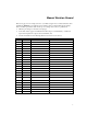
Manual Revision Record This record page is for recording revisions to your PRO-Soft QA-510 User Manual that have been published by METRON or its authorized representatives.
This page intentionally left blank.
1. About PRO-Soft QA-510 1.1 Introduction Pulse Oximetry is a state-of-the-art, non-invasive method to determine the percentage of a patient's oxygen saturation (SaO2) without having to obtain an arterial blood specimen. The instrument used for this determination is a pulse oximeter. An oximeter measures the changes in the intensity of transmitted light as blood pulsates through a patient's finger or earlobe.
“protocol.” The equipment data can be entered manually into the protocol, or it may be retrieved by PRO-Soft from other equipment files. Protocols with test results can be printed, or stored on disk. Also, the results of testing can be sent to other equipment maintenance management programs, to close a work order and update the oximeter’s service history. 1.3 About your Manual This manual is designed to assist you in the basic procedures for creating test protocols with PRO-Soft QA-510.
2. Getting Started 2.1 System Requirements The following are the minimum requirements for installation: • IBM PC/XT-compatible machine, 80486 SX 25 MHz or higher. • A 3.5" floppy drive. • An EGA, VGA, 8514, Hercules or compatible display (recommended: VGA). • 8 MB of RAM. • 1 MB of unoccupied hard disk space, plus 3 MB of free space on the drive contained the WINDOWS:\SYSTEM directory. • Microsoft Windows version 3.11 or later version. • Metron QA-510.
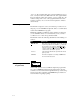
5. When setup starts, the following dialog box will appear. Type in the desired drive and directory for PRO-Soft QA510, and then click the Continue button. If you are installing PRO-Soft QA-510 for the first time, we recommend using the default drive, directory, and program group (C:\QA-510) 6. After setup is completed, a program group will be created in the Windows Program Manager called "PRO-Soft QA510," or another name you provided during installation. 7.
Be careful to enter the name and code exactly as written on the license agreement. This screen is case sensitive. 3.
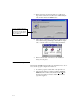
2.4 Option Settings To configure program parameters click the Option Menu, then click Edit Options. The following five-card dialog box appears: Options Edit Options In the topmost section of this box there are five tabs: PRO-Soft, QA-510, QA-MAP, Report, and Interface. By clicking one of these tabs, its corresponding card will be displayed, containing the settings available for the item described on the tab. After editing the option settings press OK to save changes, or Cancel to discard them.
printed reports. To change the defaults, enter a new operator or establishment and save by pressing OK. 2. QA-510 Tab. This tab is used for three things. Setting the communications port (COM1-4) to be utilized for initiating the QA-510 remote setting at start-up. Once entered, it becomes the default setting. To enter the serial number and firmware version of the QA-510 utilized for testing. Once entered, it becomes the default setting, and appears automatically in the headings of printed reports.
This page intentionally left blank.
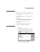
3. Testing Setup Communication between the PRO-Soft QA-510 and the QA-510 is based upon an RS-232C interface, that is standard on most modern personal computers. The operation is essentially a “master-slave” configuration, whereby the computer operates the QA-510. 3.1 Equipment Setup Attach an RS-232 (null modem/data transfer configured) cable to the 9-pin D-sub outlet port located at the rear of the QA-510. Do not attach the printer cable to the QA-510. See below.
⇑ 3. Press REMOTE CONTR. (F4) to initiate remote control. ⇑ 4. 3-2 Communication will be established when testing or downloading of presets start.
4. Sequence Testing Sequence testing enables you to perform multiple tests semi automatically. Instead of manually setting up and running one test at a time, a sequence of several tests that you desire to perform can be set up in advance of testing. Once a sequence is created you can save it for later retrieval and reuse. Up to 50 different tests can be run in each sequence. There are no restrictions on how the sequence is composed. 4.
1. 2. 2. General parameters Sequence The name of the sequence. R-Curve The oximeter probe manufacturer from the preloaded or user-defined R-curve listing. Sequence parameters Test # The test in sequential order. Ambient light The ambient light setting, which simulates motion, ambient sunlight, and 50 Hz or 60 Hz artificial light interfering with the pulse oximeter’s probe. Pigmentation The pigmentation setting (low, medium, high) Preset Simulated patient conditions. Default is Normal.
2. Alarm Limits Test Setup: a. Set the Make, Amb.L. and Pigm. parameters. b. Select the Test Parameter (SpO2, Rate or P.ampl.
This page intentionally left blank.
5. Checklists The checklist adds manually or visually performed tests and function checks to the protocols (see Chapter 7). Once created, a checklist can be edited, stored and retrieved for future use. 5.1 Checklist Form Window Form Sequence Checklist Protocol From the PRO-Soft QA-510 Main Menu select Form, Checklist. The Checklist Form Window then appears (see below). It is a table allowing for up to 30 lines, where each line contains a description of what to examine (up to 50 characters).
3. 5-2 Printing Checklists. To print a checklist, select File, Print. Then, select whether to print the checklist, or write it to a file.
6. Protocols Protocol contains a description of the oximeter being tested, and specifies an associated test sequence and checklist. It also includes a procedure file, stating special concerns for each oximeter. When saved, the results are added to PRO-Soft 510’s Protocol Database, or to QA-MAP, if installed. This database is an historical record of those protocols for which safety tests have been done with PRO-Soft.
The Protocol application window contains the following fields: 1. Equipment Information Field. This field contains text boxes that are used to describe the oximeter under test, and are also used in the safety testing report to document the test of a particular oximeter.
changes, a dialog box appears, giving you an opportunity to save the changes. When first opening the protocol application window with a new protocol these fields will be blank, indicating that no sequence or checklist is connected to the protocol. They have to be created and connected to the protocol before they will appear. 6.2 Protocol Database Protocols are saved and retrieved from the Protocol Database (see below).
a. Open loads the selected protocol into the active protocol window, allowing you to view the safety test results and other information stored in the protocol. If you already have a protocol open in the active window, and this protocol contains unsaved changes, PRO-Soft will not load the protocol selected in the database until you have responded to a dialog box prompting you to save the open protocol. b. Delete removes selected protocol(s) from the library, prompting for confirmation.
lecting File, New Protocol. Then, select Window, Tile Horizontal, so that both forms appear together. To compare the test results load the protocol corresponding to this year’s testing into one of the protocol windows, and the protocol corresponding the last year’s testing into the other window. 2. Saving Protocols. Protocols are saved to the Protocol Database. To save the active protocol, select File, Save or File, Save As.
File New protocol Load Save Save As Equipment data Procedure Import Export Print Printer Setup Exit Ctl+N Ctl+L Ctl+S Ctl+A From QA-MAP From ASCIIfile 2. Making Protocol Formats from an ASCII Text File. PROSoft can load equipment information from an ASCII text file. ASCII text files can be created on each of the oximeters for which you intend to produce protocol formats.
7. R-Curves 7.1 R-Curve Defined R-curves specify the relationship between the Red/IR ratio measured by pulse oximeters and the SpO2 value displayed. These curves are obtained by each pulse oximeter manufacturer during clinical trials. QA-510 has pre-loaded manufacturer’s R-curves (see the Appendix B for a listing). However, the operator may establish user-defined, or additional manufacturer R-curves, and these can be loaded into the PRO-Soft QA-510, and further downloaded into the QA-510.2 7.
The Simple mode window contains the following fields and buttons: 1. Sample no. This field is the sample number 2. Perform Simulation. This field contains a checkbox. If the box is checked the values will be simulated during the set of simulations. 3. Simulated SpO2 Value. This is the SpO2 value that you wish to simulate. 4. SpO2 Result. This is the field where you key in the value that is displayed on the SpO2 meter. 5. Simulate SpO2 level.
In order to generate a valid new R-Curve for use by the QA-510, you must work with a calibrated Pulse Oximeter unit or module, a known good finger probe and a calibrated QA-510. 1. 2. 3. 4. 5. 6. 7. 8. 9. 10. 11. 12. 13. 14. 15. 16. Launch PRO-Soft QA-510 on your computer and connect the NULL-Modem cable from the COM port to the QA-510. Turn on the QA-510 and the Pulse Oximeter.
17. Press the “Close” Button. This takes us back to our earlier RCurve window. 18. Go to “File” and select “Save R-Curve”. This will now save the new R-Curve to your hard drive. 19. Make sure that the desired upload location is selected in the box on the right, then press “Upload R-Curve”. The QA-510 will indicate, “Wait” while the data is uploading. Do not disconnect the cable or turn off the power on the QA-510 during the download. 20. Turn the power off on the QA-510.
File New R-Curve Load R-Curve ... Save R-Curve Save R-Curve As ... Ctl+L Ctl+S 4. SpO2 Value and R-Value. These are the fields where the SpO2 value and its respective R-value are listed. 5. New R-Value. This is where you can enter in a new R-value. Legal Values are 0-2.55. 6. Calculate R-Curve. This calculates the new R-curve based on the results from the simulation. The more simulated points that you use the more accurate the R-curve will be. 2. Transfer R-Curve.
This page intentionally left blank.
8. Troubleshooting Problem Possible Solution Communication not established between the computer and the QA-510. Check to ensure that: 1. The QA-510 is set to “Remote Control.” 2. The correct COM-Port is assigned in the Options Menu. 3. The RS-232 cable has a null modem/data transfer configuration. Test sequence grid will not accept data Check the tests to be made in the 'Tests' frame. Reports are not printed 1. Wrong printer driver. Choose the correct printer when running print report. 2.
This page intentionally left blank.
APPENDIX A: AUTO SEQUENCE CODES A1 Auto Sequence Dialog Box This dialog box (see figure below) contains a string of codes, developed from the following tables. Conventions for constructing the string are: a. There are no spaces between codes in the string. b. The Load Sequence in position ( “Q__” ) is followed in all cases by a colon. c. Each code inserted is followed by a comma ( “,” ). d. The last code is always End of sequence ( “E” ), with no punctuation thereafter.
A3 Auto Sequence Data Codes M = Pre-loaded manufacturer’s or user-defined r-curve (Example: “M01” = BCI Oxi-Pulse) Code Description Code Description M01 BCI Oxi-Pulse M09 Ohmeda M02 Criticare M10 User Defined 1 M03 Datascope M11 User Defined 2 M04 Datex M12 User Defined 3 M05 Novametrix M13 User Defined 4 M06 Marquette Electronics M14 User Defined 5 M07 Nellcor M15 User Defined 6 M08 Hewlett-Packard M16 User Defined 7 L = Ambient light (Example: “L01” = Normal) Code Desc
B = Rate from 0 to 300 BPM. This is entered in three-digit format. (For example, a BPM rate of 65 = B065) D = Delay in tenths of a seconds from 1 to 999. This is entered in threedigit format.
This page intentionally left blank.
APPENDIX B: R-Curves The following manufacturers’ R-Curves have been pre-loaded into QA-510, and are provided herein for information. B1 BCI OXI-Pulse Make: Reference Unit Serial No.: Date: BCI OXI-PULSE 3301 71000A1 320014767 04.03.97 Red Gain Setting: IR Gain Setting: Level Code Setting: 2048 1024 101 Broadband Preamp Gain: IR Preamp Gain: Broadband Trig Threshold: IR Trig Threshold: 0 dB 0 dB 0.5 V 0.5 V SpO2 R-value SpO2 R-value SpO2 R-value 100% 0.39 78% 1.03 56% 1.57 99% 0.
B2 Criticare B-2 Make: Reference Unit Serial No.: Date: Criticare Red Gain Setting: IR Gain Setting: Level Code Setting: 400 325 101 Broadband Preamp Gain: IR Preamp Gain: Broadband Trig Threshold: IR Trig Threshold: 0 dB 0 dB 0.5 V 0.5 V 04.03.97 SpO2 R-value SpO2 R-value SpO2 R-value 100% 0.44 78% 1.10 56% 1.56 99% 0.50 77% 1.12 55% 1.58 98% 0.55 76% 1.15 54% 1.60 97% 0.59 75% 1.17 53% 1.62 96% 0.63 74% 1.19 52% 1.65 95% 0.66 73% 1.21 5i% 1.67 94% 0.
B3 Datascope Accutorr Make: Reference Unit Serial No.: Date: Datascope Accutorr 3 Sat 10995F2 04.03.97 Red Gain Setting: IR Gain Setting: Level Code Setting: 2048 1024 110 Broadband Preamp Gain: IR Preamp Gain: Broadband Trig Threshold: IR Trig Threshold: 0 dB 0 dB 2V 1V SpO2 R-value SpO2 R-value SpO2 R-value 100% 0.49 78% 1.22 56% 1.75 99% 0.53 77% 1.25 55% 1.77 98% 0.56 76% 1.28 54% 1.79 97% 0.61 75% 1.31 53% 1.81 96% 0.63 74% 1.33 52% 1.83 95% 0.67 73% 1.
B4 Datex Satlite Trans B-4 Make: Reference Unit Serial No.: Date: Datex Satlite Trans 10995F2 04.03.97 Red Gain Setting: IR Gain Setting: Level Code Setting: 2048 1024 11 Broadband Preamp Gain: IR Preamp Gain: Broadband Trig Threshold: IR Trig Threshold: -14 dB -8 dB 1V 2V SpO2 R-value SpO2 R-value SpO2 R-value 100% 0.38 78% 1.09 56% 1.54 99% 0.47 77% 1.12 55% 1.56 98% 0.54 76% 1.14 54% 1.58 97% 0.59 75% 1.16 53% 1.60 96% 0.63 74% 1.18 52% 1.62 95% 0.67 73% 1.
B5 Hewlett-Packard Make: Reference Unit Serial No.: Date: Hewlett-Packard Red Gain Setting: IR Gain Setting: Level Code Setting: 480 640 96 Broadband Preamp Gain: IR Preamp Gain: Broadband Trig Threshold: IR Trig Threshold: 0 dB 0 dB 0.25 V 0.25 V 04.03.97 SpO2 R-value SpO2 R-value SpO2 R-value 100% 0.64 78% 1.29 56% 1.76 99% 0.68 77% 1.31 55% 1.77 98% 0.71 76% 1.34 54% 1.79 97% 0.74 75% 1.36 53% 1.81 96% 0.78 74% 1.38 52% 1.83 95% 0.81 73% 1.41 51% 1.
B6 Marquette Eagle B-6 Make: Reference Unit Serial No.: Date: Marquette Eagle 3000 H5LA0215G 04.03.97 Red Gain Setting: IR Gain Setting: Level Code Setting: 2048 1024 101 Broadband Preamp Gain: IR Preamp Gain: Broadband Trig Threshold: IR Trig Threshold: 0 dB 0 dB 0.5 V 0.5 V SpO2 R-value SpO2 R-value SpO2 R-value 100% 0.50 78% 1.06 56% 1.41 99% 0.53 77% 1.08 55% 1.43 98% 0.57 76% 1.10 54% 1.44 97% 0.60 75% 1.12 53% 1.46 96% 0,63 74% 1,13 52% 1,47 95% 0.
B7 Nellcor Make: Reference Unit Serial No.: Date: Nellcor N-20 207 74 771 04.03.97 Red Gain Setting: IR Gain Setting: Level Code Setting: 2048 1024 101 Broadband Preamp Gain: IR Preamp Gain: Broadband Trig Threshold: IR Trig Threshold: 0 dB 0 dB 0.5 V 0.5 V SpO2 R-value SpO2 R-value SpO2 R-value 100% 0.48 78% 1.05 56% 1.40 99% 0.52 77% 1.07 55% 1.42 98% 0.55 76% 1.09 54% 1.43 97% 0.59 75% 1.11 53% 1.45 96% 0.62 74% 1.12 52% 1.46 95% 0.65 73% 1.14 51% 1.
B8 Novametrix Oxypleth Reference Unit Serial No.: Date: Novametrix Oxyp!eth Model 520A 77 - 3766LR 04.03.97 Red Gain Setting: IR Gain Setting: Level Code Setting: 1030 1520 10 Broadband Preamp Gain: IR Preamp Gain: Broadband Trig Threshold: IR Trig Threshold: -14 dB -8 dB 1V 1V Make: B-8 SpO2 R-value SpO2 R-value SpO2 R-value 100% 0.43 78% 1.26 56% 1.76 99% 0.51 77% 1.29 55% 1.79 98% 0.59 76% 1.31 54% 1.81 97% 0.66 75% 1.34 53% 1.83 98% 0.72 74% 1.36 52% 1.
B9 Ohmeda OxySTAT Make: Reference Unit Serial No.: Date: Ohmeda OxySTAT Red Gain Setting: IR Gain Setting: Level Code Setting: 480 640 96 Broadband Preamp Gain: IR Preamp Gain: Broadband Trig Threshold: IR Trig Threshold: 0 dB 0 dB 0.25 V 0.25 V 04.03.97 SpO2 R-value SpO2 R-value SpO2 R-value 100% 0.53 78% 1.26 56% 1.77 99% 0.57 77% 1.29 55% 1.79 98% 0.60 76% 1.31 54% 1.82 97% 0.64 75% 1.34 53% 1.84 96% 0.68 74% 1.36 52% 1.86 95% 0.72 73% 1.39 51% 1.
This page intentionally left blank.
APPENDIX C: LIGHT LEVEL CODES (L-CODES) Broad Band Channel: PLUS_8dB, PLUS_0dB, MINUS_13dB, MINUS_14dB Infrared Channel: PLUS_6dB, PLUS_0dB, MINUS6dB, MINUS_8dB L1 = 0.25V L3 = 1V L2 = 0.
C-2 L(evel) Code Broad Band Gain Infrared Gain Broad Band Threshold Infrared Threshold 49 50 51 52 53 54 55 56 57 58 59 60 61 62 63 64 65 66 67 68 69 70 71 72 73 74 75 76 77 78 79 80 81 82 83 84 85 86 87 88 89 90 91 92 93 94 95 96 97 98 99 100 101 102 103 104 105 106 107 108 MINUS_14dB MINUS_14dB MINUS_14dB MINUS_14dB MINUS_14dB MINUS_14dB MINUS_14dB MINUS_14dB MINUS_14dB MINUS_14dB MINUS_14dB MINUS_14dB MINUS_14dB MINUS_14dB MINUS_14dB PLUS_0dB PLUS_0dB PLUS_0dB PLUS_0dB PLUS_0dB PLUS_0dB PLUS_0dB P
L(evel) Code Broad Band Gain Infrared Gain Broad Band Threshold Infrared Threshold 109 110 111 112 113 114 115 116 117 118 119 120 121 122 123 124 125 126 127 128 129 130 131 132 133 134 135 136 137 138 139 140 141 142 143 144 145 146 147 148 149 150 151 152 153 154 155 156 157 158 159 160 161 162 163 164 165 166 167 168 PLUS_0dB PLUS_0dB PLUS_0dB PLUS_0dB PLUS_0dB PLUS_0dB PLUS_0dB PLUS_0dB PLUS_0dB PLUS_0dB PLUS_0dB PLUS_0dB PLUS_0dB PLUS_0dB PLUS_0dB PLUS_0dB PLUS_0dB PLUS_0dB PLUS_0dB PLUS_8dB PLU
L(evel) Code Broad Band Gain Infrared Gain Broad Band Threshold Infrared Threshold 169 170 171 172 173 174 175 176 177 178 179 180 181 182 183 184 185 186 187 188 189 190 191 PLUS_8dB PLUS_8dB PLUS_8dB PLUS_8dB PLUS_8dB PLUS_8dB PLUS_8dB PLUS_8dB PLUS_8dB PLUS_8dB PLUS_8dB PLUS_8dB PLUS_8dB PLUS_8dB PLUS_8dB PLUS_8dB PLUS_8dB PLUS_8dB PLUS_8dB PLUS_8dB PLUS_8dB PLUS_8dB PLUS_8dB PLUS_0dB PLUS_0dB PLUS_0dB PLUS_0dB PLUS_0dB PLUS_0dB PLUS_0dB PLUS_6dB PLUS_6dB PLUS_6dB PLUS_6dB PLUS_6dB PLUS_6dB PLUS_6
L(evel) Code Broad Band Gain Infrared Gain Broad Band Threshold Infrared Threshold 226 227 228 229 230 231 232 233 234 235 236 237 238 239 240 241 242 243 244 245 246 247 248 249 250 251 252 253 254 255 PLUS_0dB PLUS_0dB PLUS_0dB PLUS_0dB PLUS_0dB PLUS_0dB PLUS_0dB PLUS_0dB PLUS_0dB PLUS_0dB PLUS_0dB PLUS_0dB PLUS_0dB PLUS_0dB PLUS_0dB PLUS_0dB PLUS_0dB PLUS_0dB PLUS_0dB PLUS_0dB PLUS_0dB PLUS_0dB PLUS_0dB PLUS_0dB PLUS_0dB PLUS_0dB PLUS_0dB PLUS_0dB PLUS_0dB PLUS_0dB PLUS_0dB PLUS_0dB PLUS_0dB PLUS_
This page intentionally left blank.
APPENDIX D: ERROR REPORT FORM, PRO-Soft QA-510 PRO-SOFT QA-510 SpO2 ANALYZER ERROR REPORT FORM USA 1345 Monroe NW, Suite 255A Grand Rapids, MI 49505 Phone: (+1) 888 863-8766 Fax: (+1) 616 454-3350 E-mail: metronus@aol.com FRANCE 30, rue Paul Claudel 91000 Evry, France Phone: (+33) 1 6078 8899 Fax: (+33) 1 6078 6839 E-mail: metronfrance@infonie.fr NORWAY Travbaneveien 1 N-7044 Trondheim, Norway Phone: (+47) 7382 8500 Fax: (+47) 7391 7009 E-mail: support@metron.
This page intentionally left blank.
APPENDIX E: SUGGESTION FORM, PRO-Soft QA-510 PRO-SOFT QA-510 SpO2 ANALYZER SUGGESTION FORM USA 1345 Monroe NW, Suite 255A Grand Rapids, MI 49505 Phone: (+1) 888 863-8766 Fax: (+1) 616 454-3350 E-mail: metronus@aol.com FRANCE 30, rue Paul Claudel 91000 Evry, France Phone: (+33) 1 6078 8899 Fax: (+33) 1 6078 6839 E-mail: metronfrance@infonie.fr NORWAY Travbaneveien 1 N-7044 Trondheim, Norway Phone: (+47) 7382 8500 Fax: (+47) 7391 7009 E-mail: support@metron.
This page intentionally left blank.