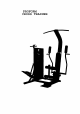
PROFORM CROSS TRAINER
TABLE OF CONTENTS IMPORTANT SAFETYPRECAUTIONS ........................................................... BEFOREYOU BEGIN ...................................................................... ASSEMBLY.................................... . ......................................... ADJUSTING THE CROSS TRAINER e .......................................................... OPERATING THE STEPPERCONSOLE .........................................................
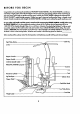
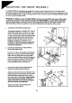
BEFORE YOU BEGIN Congratulationsfor purchasing the revolutionary PROF<:::)RM e CROSS TRAINER e. The CROSS TRAINER • combinesa multi-stotionweight syslemwith a full-size stepperto let you enjoy Irue crosstraining workouts in the convenienceof your own home. And to help you get the mosthorn everyworkout, the CROSS TRAINER • fealures the advanced PERSONAL TRAINERTM weight iralning computer.
ASSEMBLY Assembly requires two persons.To assemblethe CROSS TRAINER e, usethe included videacassettoor follow the instructionsbelow. Due to the weight of the CROSS TRAINER e, it shouldbe assembled in the location where it will be used. Placeall parts in a cleared area and remove the packing materials. Do not dispose of the Packing materials until assembly is completed.
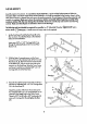
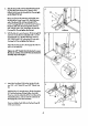
4. Slide the Brace (29) onto the threaded bolt protrud- 4 ing from the Tower Frame (10). Thread a 3/8" N/lock Nut (6} onto the threaded bolt. Do not fighten the Nylock Nut yet. Placeyour foot on the extension and slightlyraise the _ont of the Tower Frame (10). Align the lower end of the Brace (29) with the indicated 3/8" x 2 1/2" Carriage Bolt(1). Lower the Tower Frame so the Brace slidesonto the Carriage Bolt. Thread a 3/8" Nut (2) with a 3/8" Lockwasher(3) onto the Carriage Bolt.
7. Insertthe lower end of the LeftArm (15) into the left side of the Moment Arm (74). Make sure that the bracket on the end of the Left Arm is positioned as shown in Iho inset drawing. If the bracket is not positioned as shown, the Left Arm will not function propq.'ly. Align the hale in the end of the LeftArm (15) with the holes in the Moment Arm (74). Insertthe 3/4" x 4" Axle (54) into the Moment Arm and the Left Arm. Tap a 3/4' \ 15 PlasticCap (57) onto the Axle.
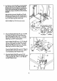
10. Wrap the Weight Cable (52) around a 2" Pulley(4). 10 Attach the Pulley to the RightArm (16) with a 3/8", x 1 3/4" Bolt(40) and 3/8" Nylock Nut (6). 0 Lay the Weight Cable (52) over a 3 1/2" Pulley (5). Attach a CableTrap (67) and the Pulleytotheside of the Upright (9) with a 3/8" x i 3/4" Bolt(40) and 3/8" N/lock Nut (6). Make sure that the Cable Trap is in the "12 o'clock" position. 11. Wrap the Weight Cable (52) under a 2" Pulley(4).
14. Attach the Seat (28) ta the Uprlght (9) wlth the two 1/4" x 3/4" Bolts(20) and a 1/4" x 2" Bolt (118). 14 15. Centerone PadTube (22) in theUpright(9), and the otherPad Tube in the LegDeveloper(23). Slide four Small Pads (171 onto the _ds of the Pad Tubes. 16. Restthe Leftand RightPedals(75, 76] on the hooks at the lower endsof the Resistance Cylinders(84). Make sumthat the hooksam fully insertedinlo the sameslolsunderIsethPedals.
DJUSTING THE CROSS TRAINER e The CROSS TRAINER e is designed to be changed ham stationto stationquickly and easily. The instructionsbelow describe how each port of the CROSS TRAINER e can be adjusted. Pleaseread these instructionscarefully before using the CROSS TRAINER e. Refer to poges 17 through 24 of this owner's manual to see how the CROSS TRAINER e should be set up for each individual exercise. IMPORTANT: For effective exercise, the CROSSTRAINER • must be set up correctly for each exercise.
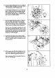
4o AITACHING THE EATBAR, ROWER BAR OR STRAP TO THE LOW PULLEYSTATION Attach the Lat Bar (36) to the Main Cable (51) with a Cable Clip (33). For someexercises,the Chain (38) shouldbe attached between the Lat Bar and the 38 Main Cable with two Cable Clips. Adjust Itm length of the Chain between Itm Lat Bar and the Main Cable so the Lat Bar is in the correct starting posl- tionfor theexerclse tobe perfarmed. 33 The Rower Bar (34) or the Strap (35) can be attached in the same manner.
OPERATING THE STEPPER CONSOLE The stepper console is designed to give you instantfeedback as you exercise on the stepper. Please read theso instruclions carefully before opomling the console. Note: Removethe clear plasticfrom the front of the console. DIAGRAM OF TIlE CONSOLE 1. LCD dlsplay--Display for all modes. 2. Mode indicators-Show which mode is currea_ selected anddisplayed. 3. MODE button--Selects modes. DIS'rANCE MODE 4.
OPERATING THE PERSONAL TRAINER COMPUTER The heart of the CROSS "IIU_NER e is the advanced PERSONA[.TRAINER weight Iraining computer.Wilh the PERSONAL TRAINER computer, you can change the weight seltingwith a touch of a bu#on. As you exercise, the computerwill measure your range of motion, show the number of Calories you have burned and keep track of the repetitionsand setsyou have completed.
Next, press theTONE or STRENGIH bunon, depending on whether you want Ibe first exerciseto be a _ or a _ exercise.The WEIGHT display willshowthe_ weight selting for the exercise that you have selected. WARNING: The recommended v_ght selting may be too high or too low for you, depending upon such factors as your _ size and physical condition, if you cannot complete the desired numbers of sets and repetitions, the weight sufllng should be decreased.
Once you have selmteclthe first musclagroup that you waat to exercise, mfm" to the lawer pad of the _. _ m mere indicatorswill be lighted, showingyou which exercise(s)to do to clevelopthe selecteclmusclegroup. One of the indicators will be flashingto show you which exerciseto do first. If you want to skip the first exercise, pressthe right arrow on the NEXT buuon until the indicator is flashing on the exercise _ you want to do first. The number of the exercise will be shown in the CALORIES/EXERCISENO.
After you have applied a decal to the exercise insertfor each of the exercism that you want to include in your first workout, fit the four tabs on the insertinto the slob in the lower part of the computer. Make sure that the insertis turned so the decals are visible. (The use of the remaining spaceson the insert will be explainedbelow.) Next,a weight,setand repetitionselfingshouldbe programmedforeach of the exercises, and theworkoutshouldbe staredon theCUSTOMSMARTCARD. Pressthe CREATEPROGRAM button.
TURNING OFF THE POWER To turn off the power, pressthe POWER button. Note: If no buttonson the computer are pressed for 30 minutes, the power will turn off automal;cally. The transformershouldbe unplugged from the 120-volt outtetduring periodsof nonuse.
EXERCISE GUIDE SAFETY The CROSS TRAINER • is a tool, and learning to use it properly is essentialfor your safely as well as the successof your exercise program. Read this owner's manual and the accompanying FITNESSJOURNAL carefully before using the CROSS TRAINER e. Remember, the information in this owner's manual and in the FITNESSJOURNAL is general in nature. For more information about exercise, consultyour physicianor obtain a reputable book about exercise.
1. BUTTERFLY (15-125 Lbs.) Musclesaffected: pectoralls major and minor, deltoids Refer to adjuslmont 2 on page 8 of thisowner's manual. Change the arms to the buttmBy mnde. Sit on the seat and hold the pods on the arms as shown; your arms shouldbe bent at 90* angles. Keep your back straight. Pressthe arms'together until the pads touch. Returnto the starling position. 2. BENCH PRESS (30-250 Lbs.
6. LATERALARM RAISE (15-125 Lbs.) Muscles affected:deltoids, trapezius Refer to adjustment4 on page 9 of thls owner's manual. Altach the strap ta II_ low pulley station. Stand with your side toward the CROSS TRAINER • with your feet on the foot plate. Hold the slmp with an overhand grip with your arm at your side. Keep your back straight. Raise the strap to the side until your hand is level with your shoulder as shown. Returnto the startingposition. 7. SEATED ROW--CLOSE GRIP (15-125 Lbs.
11. LEG EXTENSION (15-125 Lbs.) Musclesaffected: quadriceps Sit on the seat and positionyour feet under the pads on the leg developer. Keep your back straight.Raise the leg developer until your legs are straight. Return to the starting position. 12. HIP ABDUCTION (15-125 Lbs.) Musclesat_eded: abductor, gluteusmedius Refer to adjustment4 on page 9 of this owner's mQnual. Attach the strap to the low pulley station. Stand with your side toward the CROSS TRAINER e with or)e foot on the foot plate.
16. SINGLE LEG CURL (15-125 Mu_les otT_I: Lbs.) I_msh'ing,_strocnemius Stand facing the CROSS TRAINER e and restthe back of one leg against the lower pad on the leg developer. Raise the leg developer as far as possibleby bending your leg as shown. Relum to the starting position. 17. ABCRUNCH (15-125 Lbs.) Muscles alTm'tod:rectusabdominus, upper abdominals Refer to.adjuslment3 on page 8 of thisowner's manual. Attach the strap to the high pulley station.
A. SIDE BEND (15-125 Lbs.) Musclesaffected: latissimusdorsi, biceps, posterior deltoids Refer to adjustment4 on page 9 of this owner's manual. Attach lee strap to the !ow pulley station. Stand with your side toward the CROSS TRAINER • with one foot on Ifle foot plate. Hold the strap with an overhand grip with your arm at your side. Keep your back sh'aight.Bendtoward the side as shown. Returnto the starling pasition: B. LAT PULL-DOWN--CLOSE GRIP (15-125 Lbs.
F. SINGLE ARM BENT ROW (15--125 Lbs.) _Musclesat_ecled:biceps,brachioradials,deltoids, h'apez.ius,lalissimusdorsi,rhomboids Refer to adjustment 4 on page 9 of this owner's manual. Altoch the strap to the low pulley station. Stand with your feet on the foot plc_ and bend forward as shown. Hold the strap with on overhand grip with your arm extended downward. Keep your back straight.Pullthe strap toward your stomach.Returnto the starting position. G. SEATED ROW--WIDE GRIP (15-125 Lbs.
K. BENT ISOLATION CURL (15--125 Lbs.) MusclesatTected:biceps, brachioradials Rear to adjustment4 on page 9 oFthis owner's manual. Altach the strap to the low pulley station. Stand with your side toward the CROSS TRAINER e, place one foot on the foot plate and bend forward as shown. Hold the strap with an underhand grip with your e[baw restingagainst your knee and your arm extended downward. Pull the strap up until your hand is level with your chest. Returnto the starting position. L.
P. BENT LATERAL ARM RAISE (15-125 Lbs.) MusclesaFfeded:deltoids,trapezius Refer to adjustment4 on page 9 of this owner's manual. Altach the strap to the low pulley station. Stand with your side toward the CROSS TRAINER e, place one foot on the foot plate and bend for_vardas shown. Hold the strap with an overhand grip with your arm at your side. Keep your back straight. Raise the strap to the side until your hand is level with your shoulder. Returnto the starting position. Q. DEAD LIFT(15-125 Lbs.
TROUBLE-SHOOTING AND MAINTENANCE inspectand tighten all parts each time you usethe CROSS TRAINER e. Replace any worn parts immediately. Outside surfaces of the CROSS TRAINER • can be cleaned using a damp cloth and mild detergent. Keep all liquidsaway from Ihe stepper consoleand the PERSONALTRAINERcomputer.Most CROSSTRAINER• problems can be solved by following Itm stepsbelow. Find the applicable symptomand follow the step(s) listed. If further assistanceis needed, .
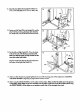
b° If the LCD display becomesdim, the 1.5-voh watch balteries in the Stepper Console (88) shouldbe replaced. Using a short phillipsscrewdriver, Backof Ste_ Console remove the two screws attaching the back of the StepperConsole. Using the screwdriver, carefully push the two batteries out of the battery clips; be careful to note which way the batteries are turned. Inserttwo new 1.5-volt watch batteries into the 1.5-Voh Watch Batteries battery clips. Reattach the back of the Stepper Console. 4.
ORDERING REPLACEMENT PARTS To order replacement parts, simply call our CustomerServiceDepartment toll-free at 1-800-999-3756, Monday through Friday, 6 a.m. until 6 p.m. Mountain Time (excluding holidays). To help usassistyou quickly, please be prepared to give the following information: 1. The MODEL NUMBER of the product (DR852040). 2. The NAME of the product (PROFORM®CROSSTRAINERe). 3. The SERIALNUMBER of the product (see BEFOREYOU BEGIN on page 2 of this owner's manual). 4.