
Owner`s manual
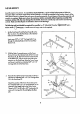
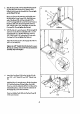
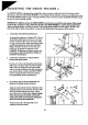

7. Insertthe lower end of the LeftArm (15) into the left
side of the MomentArm (74). Make sure that the
bracket on the end of the LeftArm is positionedas
shown in Iho inset drawing. If the bracket is not
positioned as shown, the LeftArm will not function
propq.'ly.
Align the hale in the end of theLeftArm (15) with
the holes in the Moment Arm (74). Insertthe 3/4" x
4" Axle (54) intothe Moment Arm and the LeftArm.
Tap a 3/4' PlasticCap (57) ontothe Axle.
Attach the RightArm (16) in the same manner.
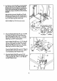
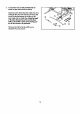
8. Wrap the Weight Cable (52) under a 3 1/2" Pulley
(5). Attach the Cable Trap (67) and Pulleyto the
back of the Upright (9) with a 3/8" x 1 3/4" Bolt
(40) and 3/8" Nylock Nut (6). Make surethat the
Cable Trap isin the "7 o'clock_ position.
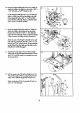
Lay the Weight Cable (52) aver a 3 1/2" Pulley(5).
Attach a Cable Trap (67) and the Pulleyto the [eft
side of the Upright (9) with a 3/8" x 1 3/4" Bolt
(40) and 3/8" Nylock Nut (6). Make surethat the
Cable Trap is in the "12 o'clock"position.
Wrap the Weight Cable (52) around a 2" Pulley(4).
Attach the Pulleyto the LeftArm (15) with a 3/8" x
1 3/4" Bolt(40) and 3/8" N/lock Nut (6).
°
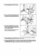
Wrap the Weight Cable (52) around a 2 3/4"
Pulley(13). Attach the Pulleytothe indicated bracket
an the Upright (9) with a 3/8 = x 1 3/4" Bolt (40)
and 3/8" Nylock Nut (6).
9
40
\
15
/"
/
/
/
/
(_'_rrect position oFArms
' against Moment Arm
74
INCORRECT CORRECT
67
5 5
67
5