
User guide
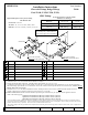

Part Numbers:
51016
Dodge Pickup Truck - Full Size 1967 - 1993
Spare tire carrier will have to be modified to retain under vehicle stowage.
Spare tire can also be relocated elsewhere on the vehicle.
Rev. A6-27-06N51016Sheet 5 of 5
z 2001, 2006 Cequent Towing Products
Lock Washer 1/2Qty. (2)Spacer 1/4 X 1.50 X 2.00Qty. (12)
5
Bolt 1/2-13 X 2.25Qty. (2)Conical Washer ½Qty. (6)
6
Hex Nut 1/2-13Qty. (6)
7
Nut M12 X 1.75Qty. (2)Bolt 1/2-13 X 2.00Qty. (4)
4
Spacer 7/16 X 1.00 X 2.00Qty. (2)
Flanged Locknut 1/2-20Qty. (6)
3
Bolt M12 X 1.75 X 45Qty. (2)
9
Harden Flat WasherQty. (8)
2
Spacer 1/4 X 1.00 X 2.00Qty. (4)
8
Bolt 1/2-20 X 1.50Qty. (6)
1
Note: check hitch frequently, making sure all fasteners and ball are properly tightened. If hitch is removed, plug all holes in trunk pan or other body panels to
prevent entry of water and exhaust fumes. A hitch or ball which has been damaged should be removed and replaced. Observe safety precautions when working
beneath a vehicle and wear eye protection. Do not cut access or attachment holes with a torch.
This product complies with safety specifications and requirements for connecting devices and towing systems of the state of New York, V.E.S.C. Regulation V-5
and SAE J684.
12
13
11
Installation depends on vehicle configuration:
Configuration 1:
8' bed, 2 & 4 wheel drive, regular & extended cab
Configuration 2:
6' bed, 2 & 4 wheel drive
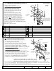
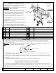
Configuration 1 - All holes require drilling
1. Position and center the receiver assembly on vehicle frame.
Locate rearmost slot in receiver 1" forward from the edge
of the large existing hole at the end of the frame. This is
required so that the forward attaching flange does not ride
on the crossmember rivet. Clamp receiver to the frame.
2. Center receiver crosstube assembly on vehicle and tighten
the 1/2-20 hex bolts installed as shown on page 1 to
90 lb.-Ft.(122 N*M)
3. Using slots in brackets as templates, center punch and drill six
(6) 1/2" diameter holes in frame. Install fasteners as shown for
configuration 1.
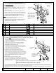
Configuration 2 - uses existing holes
1. Position and center receiver over large existing hole at the end of
the frame. Center and forward slots will match with existing
holes. Secure with fasteners as shown for configuration 2.
2. Center receiver crosstube assembly on vehicle and tighten the
1/2-20 hex bolts installed as shown on page 1 to 90 lb.-Ft. (122 N*M)
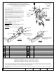
1. Attachment holes must be drilled for most applications. In some cases existing holes in frame may line up with some of the holes
in the receiver side brackets. When holes do not match precisely, file or grind material from the vehicle frame to match the hole
in the receiver side bracket.
Warning
: do not correct hole mismatch by drilling, because drill can suddenly bind causing drill motor to "kick back" or drill
bit to break, possibly resulting in personal injury.
General Notes
!
2. When positioning receiver on vehicle frame, make sure that the crosstube assembly does not contact any gas tank supports or spare tire
hanger brackets if vehicle is so equipped.
3. Be careful to avoid drilling into the fuel tank, wires and fuel or brake lines that are sometimes located inside the vehicle frame sections.
4. Deburr all edges of any holes drilled through frame and/or crossmembers. Proper deburring will ensure that fasteners and side brackets
will sit flat.
5. Always wear safety glasses when drilling.
6. License plate mounting bracket will have to be relocated on vehicles without a factory installed bumper.
Slot in side Bracket
Hole in vehicle frame
File or grind “shaded” frame material away
6
7
6
6
7
4
5
4
2
5
4
9
5
Large
existing hole
Crossmember
and rivet
Tighten all 1/2-20 GR5 fasteners with torque wrench to 90 Lb.-Ft. (122 N*M)
Tighten all 1/2-13 GR5 fasteners with torque wrench to 75 Lb.-Ft. (102 N*M)
Tighten all M12 CL10.9 fasteners with torque wrench to 75 Lb.-Ft. (102 N*M)
Configuration 2.
Configuration 1.
11
Form: F205 Rev A 5-6-05