INSTRUCTION MANUAL 15K Fifth Wheel Hitch DEALER/INSTALLER: (1) Provide this Manual to end user. (2) Physically demonstrate hitching and unhitching procedures in this Manual to end user. (3) Have end user demonstrate that he/she understands procedures. END USER: (1) Read and follow this Manual every time you use hitch. (2) Save this Manual and Hitch Warning Hang Tag for future reference. (3) Pass on copies of Manual and Hitch Warning Hang Tag to any other user or owner of hitch.
WARNING: Failure to follow these instructions may result in death or serious injury! INDEX 1. GUIDELINES FOR MATCHING TOW VEHICLE AND TRAILER 2. ASSEMBLY INSTRUCTIONS 3. BEFORE EACH TRIP 4. HITCHING PROCEDURE 5. PULL TEST 6. UNHITCHING PROCEDURE 7. MAINTENANCE 8. Cequent Towing Products THREE YEAR LIMITED WARRANTY 9. GENERAL CHASSIS MOUNTING INSTRUCTIONS 10. BASE RAIL APPLICATIONS P. 2 P. 4 P. 5 P. 5 P. 8 P. 8 P. 9 P. 23 P.
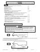
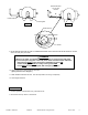
4. Trucks come in many different configurations. This hitch is designed for use in light trucks such as the Ford F-Series, the Chevy Silverado and the Dodge Ram. This hitch is recommended for use with long bed (8ft) light trucks for the best combination in trucktrailer turning clearance. Rule of thumb: The distance from the back of the truck cab to the center of the rear truck axle (“X” in Fig. 3), should be approximately 4 inches greater than one-half the trailer width (“Y” in Fig.3) RV TRAILER Fig.
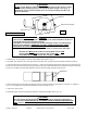
WARNING: Do Not use this hitch for towing a trailer with a pin box that could come into contact with or interfere with the pad lock or the handle tab when turning! (See Fig. 6) If the pin box contacts the hitch handle, tab or its lock when turning, the trailer may become unhitched. KING PIN BOTTOM OF PIN BOX PAD LOCK Fig.
7. Lubricate yokes in head support (27) with heavy oil or chassis grease. 8. Install outer tubular handle (35) over solid inner handle (17) and pin together with cotter pin (34). Bend cotter pin to hold in place. 9. Place head assembly (26) into yokes in head support (27) and secure with two short pull pins (23), with grooved end toward tailgate of truck. Install spring cotter pins (12) into grooves in pull pins. BEFORE EACH TRIP: 1.
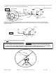
3. Pull handle out (A) and forward (B) so that the handle rests in the handle groove on the side of the hitch head and cocks it open. (See Fig. 10). The hitch is now ready to accept the trailer king pin. Locking Bar Retracted Handle Groove Fig. 10 B A Handle Tab B Sleeve King pin Handle 4. With locking bar in the open position (See Fig. 10), back truck slowly into trailer king pin until locking bar slides behind king pin.
6. With: •All trailer wheels still firmly blocked,and •Landing gear still resting on firm ground and supporting trailer weight, and •Truck stationary and in park with emergency brake on: Visually check that bottom of pin box is resting on top of the hitch. THERE SHOULD BE NO SPACE BETWEEN THESE SURFACES (See Fig. 13). If space exists, (See Fig. 14) trailer has not been properly hitched. DO NOT TOW! Instead, repeat above steps until trailer is properly hitched.
PULL TEST WARNING: Failure to perform this test may result in death or serious injury! 1. With: •All trailer wheels still firmly blocked, and •Trailer land gear still resting on firm ground and supporting trailer weight and, •Truck stationary and with emergency brake on: Return to cab of truck and release truck’s emergency brake. Apply trailer brakes. After making sure no one is between truck and trailer, try to pull trailer slowly forward with the truck.
Pull Handle all the way out and forward B A Handle Tab Locking Bar Fig. 16 Fig. 17 Handle Groove B Handle 9. AFTER MAKING CERTAIN NO ONE IS STANDING BETWEEN TRUCK AND TRAILER OR IN FRONT OF TRUCK, drive truck slowly away from trailer.
GENERAL INSTRUCTIONS FOR BASE RAIL INSTALLATION TOOLS 3/16" drill 17/32" drill 1” drill (Some Dodge application only) 3/4" Socket & Open End Wrench 100 lb-ft Torque Wrench "C" Clamps 1. The following instructions should be used to mount the 5th wheel. Care and attention to detail will ensure a quick quality installation. Check parts against parts list to become familiar with parts in kit. (See Fig. 19) 2.
10. Drill two holes in frame for each bracket. Select the holes which will give the greatest spread between bolts. Install eight 1/2”-13x1-3/8” ribbed neck bolts, (threads pointing out), lock washers, and hex nuts. Tighten nuts until bolt heads seat. Lubrication of knurls of all rib neck bolts is recommended. Note: On vehicles with heavy duty suspensions, check for interference with bolts where brackets are mounted to frame.
GM ‘99 Silverado, Sierra (not Sierra Classic) models GM ‘00 and newer Silverado,Sierra models including HD models CAUTION! Read pages 2-3 of these instructions before starting installation. Failure to do so could result in significant vehicle damage! IMPORTANT NOTES FOR THIS INSTALLATION: ROW 4 ROW 3 ROW 2 ROW 1 1. Find parallel rows of bed sill spot welds in bed of truck. No drilling should be done in the ~4” between parallel rows of spot welds where the bed sill sits.
CHEVROLET/GMC 88-98 / 92-98 4-DOOR / ‘99 SILVERADO SIERRA CLASSIC (WITH TAPERED FRAME) (RED TURN SIGNALS) CAUTION! Read pages 2-3 of these instructions before starting installation. Failure to do so could result in significant vehicle damage! IMPORTANT NOTES FOR THIS INSTALLATION: ROW 4 ROW 3 ROW 2 ROW 1 1. Find parallel rows of bed sill spot welds in bed of truck. No drilling should be done in the ~4” between parallel rows of spot welds where the bed sill sits.
Chevrolet 73 to 87 / 73 to 92 4-door (GMC) (34” Straight, with Outside Shock Absorbers) CAUTION! Front of Vehicle ROW 4 ROW 3 ROW 2 ROW 1 Read pages 2-3 of these instructions before starting installation. Failure to do so could result in significant vehicle damage! Rear Edge of Truck Bed Drill through bed and truck frame Each base rail must have a bolt in either of the marked center holes. Check for obstructions before drilling.
Chevrolet 73 to 87 / 73 to 92 4-door (GMC) (34” Straight, with Inside Shock Absorbers) CAUTION! ROW 4 ROW 3 ROW 2 ROW 1 Read pages 2-3 of these instructions before starting installation. Failure to do so could result in significant vehicle damage! Front of Vehicle Rear Edge of Truck Bed Each base rail must have a bolt in either of the marked center holes. Check for obstructions before drilling. 34 7/8” Long Box and Short Box Measure from Rear Edge of truck bed to rear edge of base rail.
Ford ‘97 to ’03 F-150 & F-250 8500 GVW AND UNDER and ’04 Heritage Series Body Style Note: ’04 AND NEWER F-150 requires Bracket Kit 58241 (Sold Separately) CAUTION! Read pages 2-3 of these instructions before starting installation. Failure to do so could result in significant vehicle damage! IMPORTANT NOTES FOR THIS INSTALLATION: 1. Long and Short Brackets on Driver’s Side may need to be switched to avoid interference with exhaust hanger. ROW 4 ROW 3 ROW 2 ROW 1 2.
FORD F-150 & F-250 THROUGH ’96 / ‘97 F-250 OVER 8500 GVW, F350 THROUGH ’97 / 1999 & NEWER F-250 & F-350 SUPERDUTY CAUTION! Read pages 2-3 of these instructions before starting installation. Failure to do so could result in significant vehicle damage! IMPORTANT NOTES FOR THIS INSTALLATION: 1. On short bed vehicles, attach Driver’s Side forward bracket on Row 2 to avoid interference with fuel lines. 2. On vehicles with overload springs, switch position of long and short brackets.
DODGE ‘02 AND NEWER 1500 / ‘03 AND NEWER 2500 WITHOUT OVERLOAD BRACKETS (‘03 2500 WITH OVERLOAD AND 3500 REQUIRE BRACKET KIT 58186) CAUTION! ROW 4 ROW 2 ROW 1 3. Do not drill thru both walls of frame. Drill only thru wall of frame to which bracket is mounted. 4. It is very important that brackets in Row 2 are against rear side of Bed Sill as shown. Due to dimensional instability in Bed Sill placement with the Dodge truck, interference could result when drilling in Row 3.
DODGE ‘03 AND NEWER 2500 AND 3500 (REQUIRES 58186 BRACKET KIT ) CAUTION! Read pages 2-3 of 30035 instructions before starting installation. Failure to do so could result in significant vehicle damage! ROW 4 ROW 3 ROW 2 3. Do not drill thru both walls of frame. Drill only thru wall of frame to which bracket is mounted. 4. It is very important that brackets in Row 2 are against rear side of Bed Sill as shown.
DODGE ‘94 to ‘01 1500 / ‘94 to ‘02 2500/3500 (FULL SIZE, SHORT AND LONG BOX) CAUTION! Read pages 2-3 of these instructions before starting installation. Failure to do so could result in significant vehicle damage! ROW 4 ROW 3 ROW 2 ROW 1 IMPORTANT NOTES FOR THIS INSTALLATION: 1. It is very important that brackets in Row 2 are against forward side of bed sill as shown below. Due to dimensional instability in bed sill placement with the Dodge truck, interference could result when drilling in Rows 3 or 4.
DODGE THROUGH 93 (FULL SIZE) CAUTION! Read pages 2-3 of these instructions before starting installation. Failure to do so could result in significant vehicle damage! IMPORTANT NOTES FOR THIS INSTALLATION: ROW 4 ROW 3 ROW 2 ROW 1 1. May need to move base rail location +/- 1/2” to ensure frame brackets do not interfere with bed sills. Rear Edge of Truck Bed Front of Vehicle 29 5/8” Long Box and Short Box Each base rail must have a bolt in either of the marked center holes.
DODGE ’94 to 2004 DAKOTA CAUTION! Read pages 2-3 of these instructions before starting installation. Failure to do so could result in significant vehicle damage! IMPORTANT NOTES FOR THIS INSTALLATION: 1. Find parallel rows of bed sill spot welds in bed of truck. No drilling should be done in the ~4” between parallel rows of spot welds where the bed sill sits. ROW 4 ROW 3 Cut Off 1" ROW 2 ROW 1 2. Cut 1” from top flange of brackets. Under bed, mount brackets with flanges facing out. 3.
TOYOTA TUNDRA 2000 & NEWER (STANDARD CAB LONG BOX ONLY) CAUTION! Read pages 2-3 of these instructions before starting installation. Failure to do so could result in significant vehicle damage! ROW 4 ROW 3 ROW 2 ROW 1 NOTE: For Toyota Tundra application, part #58197 spacer kit is required. Stack (1) 3/16” and (1) 5/16” thick slotted spacer to avoid crushing of truck bed. Front of Vehicle Rear Edge of Truck Bed Each base rail must have a bolt in either of the marked center holes.
NOTES THREE YEAR LIMITED WARRANTY Cequent Towing Products warrants its 5th Wheels from date of purchase against defects in material and workmanship under normal use and service, ordinary wear and tear excepted, for 3 years of ownership to the original consumer purchaser when a Cequent Towing Products mounting kit is used. Products used by professional hauler’s are subject to Towing Product’s limited One (1) year warranty.
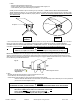
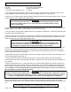
36 35 Fig. 19 34 18 37 26 17 13 27 23 29 31 28 14 15 12 25 5 11 14 3 15 10 9 1 7 8 6 4 15K 5TH WHEEL PCS. 11. LONG PULL PIN (4) 12. SPRING COTTER PIN (6) 13. LOCKING BAR (1) 17. SOLID INNER HANDLE (1) 18. HANDLE TAB (1) 23. SHORT PULL PIN (2) 26. 5TH WHEEL HEAD (1) 27. HEAD SUPPORT (1) 28. SIDE BRACKETS (2) 29.1/2”X4 1/2” BOLTS (4) 31. 1/2” LOCK NUTS (4) 34. DRIVE PIN (1) 35. HANDLE, TUBE (1) 36. HANDLE GRIP (1) 37.