
Product Manual

• The control unit on S3 Series and S5 Series pumps must receive 115V AC +/- 5% and 60
Hz from the AC outlet. Lower voltage may cause the power failure alarm to activate.
• These primary pumps will not provide protection during a power outage. With the risk of
property damage from high water levels, the addition of a PHCC Pro Series battery back-
up sump pump system is highly recommended.
• After the initial installation, be sure to check the operation by filling the sump with
water and observing the pump operation through one full cycle.
• For continuous duty operation, the pump must be submerged at least 3/4 of the depth of
the pump at all times.
• In instances where the discharge line is exposed to freezing temperatures, the pipe must
be sloped downward so any remaining water will drain out. Failure to do so will prevent
water from exiting the sump and damage the pump if the line freezes.
Installation Instructions
Prior to Installation
1. Visually inspect your pump. Products may be damaged during shipping. If the product
has been damaged, contact your place of purchase or Glentronics, Inc. before installation.
2. Thoroughly read the instructions provided to learn specific details regarding installation
and use. This manual should be retained for future reference.
Installing the Pump
1. Use a pit that conforms to all local codes and is large enough to accommodate the pump
and float switch. The minimum requirements for pumps with the double float assembly are
10⬙ in diameter and 14⬙ deep. However, larger sump pits are preferred, since they will
extend the discharge cycle and reduce the number of times the pump turns on.
2. Clean the pit of all debris. The pump’s intake screen must be kept clear.
3. The pump should not be set directly onto a clay, earthen, or sand base. You may install
bricks or blocks under the pump to provide a solid base.
4. The pump should be level.
5. Install discharge plumbing according to
local, regional and state codes. Rigid
PVC pipe is recommended.
6. The sizes of the discharge outlets on the
pumps vary from 1
1
⁄4⬙ to 2⬙. Try to match
the size of the discharge pipe to the size
of the outlet on the pump to maintain
the optimum pumping capacity. If you
are using a PHCC Pro Series pump with a
2⬙ discharge outlet to replace a pump in
a system that has been plumbed with
1
1
⁄2⬙ pipe, you may use the adapter
included with the system to reduce the
size of the discharge outlet to 1
1
⁄2⬙.
However, this will reduce the capacity of
the pump.
7. An in-line check valve is recommended to
prevent back-flow. This check valve is
mandatory when sharing a discharge line
with another pump (i.e. a back-up pump
or a second primary pump). Note: When
using a check valve, an air bleed hole of
1
⁄8⬙ (3.2mm) for the S3 & S5 Series and
3
⁄16
⬙
(4.76mm) for the E7 Series needs to
be drilled in the discharge pipe. The best
location is about 3
⬙
above the top of the
discharge outlet. The hole must be drilled
below the check valve. A small stream of
water will escape through this air bleed hole when the pump is running, so the hole should
be drilled on an angle toward the bottom of the sump pit.
8. Install a gate valve or ball valve as required by any codes.
9. Secure the power cord to the discharge pipe with wire ties or clamps to prevent
interference with the float assembly.
10. A pit cover is recommended for all installations as a safety measure, and to prevent
debris from falling into the pit.
11. A cover is required in all sewage pump installations with gas-tight seals to contain
gases and odors. A vent pipe should be added in any sewage installation.
12. In instances where the discharge line is exposed to freezing temperatures, the pipe must
be positioned in a downward slope so any remaining water will drain away. Failure to
do this will prevent water from exiting the pit and damage the pump if the line freezes.
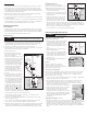
Installing the Double Float
(included with S3 and S5 Series pumps)
The PHCC Pro Series double float switch is easy to
install by using the enclosed metal hose clamp.
1. Hold the float switch to the discharge pipe so
the cage is below the bracket.
2. Secure the float to the pipe with the enclosed
hose clamp, but do not completely tighten the
clamp at this time.
3. Position the float switch to a level where the
bottom of the float cage is no lower than 3⬙
above the bottom of the pump and no higher
than 1⬙ below the top of the pit. To avoid
debris pouring into the float, it should be positioned on the side of the discharge pipe
opposite the drain tile. Note: It is important to mount the float below the drain tile that
empties into the pit. Mounting it above the drain tile would allow water to fill the drain
tile before the pump is activated to pump out the water.
4. Once the float switch is in the desired position, tighten the clamp.
Connecting the Pump and Controller
Deluxe Dual Float Controller Model # DFC2
(included on S3 and S5 Series)
1. Mount the controller to the foundation, drywall
or a stud through the 4 holes on the cabinet
using the proper mounting hardware for the
application. The controller should be mounted
at least 4⬘ from the floor and within 8” of the
outlet.
2. Open the plastic door on top of the unit and
install a 9V alkaline battery.
3. Plug the control box into a properly grounded,
3-prong receptacle (preferably with ground fault
circuit interrupt). Then, plug the pump into
the receptacle on the control box. Do not use
an extension cord.
4. Make sure the Power Failure Alarm slide switch
is in the ON position.
E7 Series
The E7 Series pumps do not come with a
controller. Plug the pump directly into a
properly grounded, 3-prong receptacle (preferably
with ground fault circuit interrupt).
Connecting to a Security System
The Deluxe Controller (Model DFC2) includes a terminal on the right side of the control box
to connect to a security system or other alarm devices. There are (3) three positions for
wire connections on this terminal: N.O. – normally open, N.C. – normally closed, and
Common. (Refer to photo on next page)
1. Check your security system to determine whether an open (no contact) or closed (making
contact) connection is needed to activate the alarm.
2. The security system will provide (2) two connection terminals to extend wires to the
control terminal. Strip two wires 1/4” each. Connect either wire to the common
terminal. To secure the wire into the terminal, insert the exposed wire into the hole on
the side of the terminal next to the screw marked
common. Turn the screw a few turns to lock-in the wire.
3. If the security system requires a closing of a contact to
activate the alarm, secure the other wire into the
terminal hole labeled N.O. (normally open). If the
security system requires an opening of a contact, secure
the wire into the terminal hole labeled N.C. (normally
closed). Note: Only the “AC power out” and ‘Float raised
for 10 minutes” alarms will activate the remote
terminal signal.
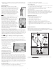
Completing the Installation (all models)
1. After the initial installation, be sure to check the pump operation by filling the sump
with water and observing the pump through one full cycle. When using the dual float the
pump should run for 10 seconds after the lower float drops. Note: When the pump
activates, it should have a “normal pumping” sound. Any abnormal sound, vibration, or
lack of output is the signal of a problem. Stop the pump and refer to the troubleshooting
guide.
WARNING
WARNING
NOTICES
PUMP
WIRE
AIR BLEED
HOLE
FLOOR
JOIST
S
LOPE
PIPE
DOWN
DISCHARGE
PIPE
GATE
VALVE
UNION/CHECK
VALVE
PRO SERIES
PUMP
DUAL
FLOAT
BRICKS
DRAIN TILE
FLOAT WIRE
AC
OUTLET
DELUXE DUAL
FLOAT CONTROLLER
MOUNTED ON WALL
PIT COVER
PUMP
WIRE
AIR BLEED
HOLE
F
LOOR
JOIST
SLOPE
PIPE
DOWN
DISCHARGE
PIPE
GATE
VALVE
UNION/CHECK
VALVE
P
RO SERIES
PUMP
DUAL
F
LOAT
B
RICKS
DRAIN TILE
F
LOAT WIRE
AC
OUTLET
DELUXE DUAL
FLOAT CONTROLLER
MOUNTED ON WALL
PIT COVER
PUMP
WIRE
AIR BLEED
HOLE
FLOOR
JOIST
SLOPE
PIPE
DOWN
DISCHARGE
PIPE
GATE
VALVE
UNION/CHECK
VALVE
PRO SERIES
PUMP
DUAL
FLOAT
BRICKS
DRAIN TILE
FLOAT WIRE
AC
O
UTLET
DELUXE DUAL
F
LOAT CONTROLLER
MOUNTED ON WALL
PIT COVER
This installation must be in accordance with the National
Electric Code and all applicable local codes and ordinances.
Make sure the outlet is single phase, 115V and 60HZ for all
the pump installations.
P
UMP
WIRE
2