
Product Manual

2. Replace the pit cover making sure not to pinch or crimp the pump wire with the cover.
The pit cover either has a ‘hole punch’ that will allow the cord to be passed through or
one can be drilled.
Product Operation
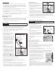
Dual Float Switch (included with controller model DFC2)
The dual float switch contains two large floating rings enclosed
within a protective cage. Water will lift the bottom float by a
1
⁄4⬙, which will activate the pump. If for any reason the lower
float does not activate the pump, the water will rise and
activate the second switch. As the pump evacuates the water
from the pit the floats will drop. The pump will run for an
additional 10 seconds to extend the cycle after the lower float
drops. Note: When mounting the float switch, position the
bottom of the cage at the height you want the pump to
activate.
Deluxe Dual Float Controller Model # DFC2 (S3 and S5 Series)
The benefit of this controller is that it will sound an alarm
when problems exist regarding the ability of the sump pump
to keep the basement dry.
The PHCC Pro Series Deluxe Dual Float Controller features a
series of warnings (audible and visual) that pinpoint
potential problems with the pump, switch and power
conditions. The controller will sound an alarm when power
has been interrupted, when the pump has run for more than
10 minutes continuously, or when the 9V battery is low. The
9V battery (sold separately) runs the controller during a
power outage, allowing it to sound an alarm if the circuit
breaker trips, the controller is not plugged in securely, or the
homes power is interrupted. Note: The 9V battery will only
power the switch, not the pump.
Operating the Pump in a Continuous Duty Application
The PHCC Pro Series pumps are rated for continuous duty and may be used in applications
requiring continuous pumping including fountains, ponds, etc. For use in any continuous
duty application the pump should be plugged directly into the wall outlet without the use of
a controller. The outlet must be a single phase properly grounded 3-prong receptacle, 115V,
60HZ (preferably with ground fault circuit interrupt). For continuous duty operation, the
pump must
be submerged at least 3/4 of the depth of the pump at all times.
Understanding the Warnings and Alarms (Model # DFC2)
AC power is out
There are several causes for power failure. The most common are a power outage by the
electric company or a tripped circuit breaker. Although the deluxe controller can not run
the pump, it will sound an alarm indicating the loss of power. This will allow the
homeowner to address the problem. If this warning light and alarm are on, the control box
is not receiving AC power for one of several reasons:
1. The control box is not plugged in.
2. The power to the house is out.
3. The circuit breaker to that outlet
has been tripped.
4. The ground fault interrupter has been
tripped for that outlet.
5. A power brownout is taking place.
Note: A PHCC Pro Series battery backup
sump pump system can protect the
basement during a power outage. It
will automatically activate a separate
12-volt battery powered pump, which will keep the basement dry until power is restored.
Power Failure Alarm slide switch
When the controller is not receiving AC power, the monitoring features and the audible
alarms are powered by the 9-volt battery. This type of battery will power the controller for
many hours, but not indefinitely. Once the source of the AC power alarm is determined, it is
suggested that the Power Failure Alarm slide switch be turned to the OFF position until the
power is restored. This will preserve the battery and silence the alarm. When AC power is
restored, slide this switch back to the ON position. Note: If the AC power is restored and the
slide switch is in the OFF position, the alarm and light for the 9-volt battery warning will
activate, even if the battery is good. This is a reminder to reset the alarm. Slide the switch
to the ON position. If the battery is good, the light will go out. If the alarm continues to
sound, replace the battery.
The system is operating
This light should be ON and flashing at all times. It is included to indicate that the system
is monitoring the sump conditions. This light will not illuminate when:
1. The power is out and the Power Failure Alarm slide switch is in the OFF position.
2. The power is out and the 9V battery is discharged.
3. The controller is not functioning. Contact Glentronics service department.
The 9-volt battery is low
1. The 9-volt battery located in the top of the control box is coming to the end of its useful
life. Replace it with a new 9-volt alkaline battery.
2. The Power Failure Alarm switch is in the OFF position. It must be in the ON position at
all times, except when silencing an actual power failure condition.
Pump or float problem
This key feature monitors the time that the float switch is continuously up or in the
activated position. It is unusual for a pump run for 10 or more minutes continuously. This
can occur for many different reasons. Either the float is stuck in the up position, there is a
mechanical problem with the pump, or there is a problem with the plumbing connections.
Please refer to this manual’s Troubleshooting Guide on the following page.
Maintenance Check List
Maintenance should be performed 1-2 times per year.
1. Remove all debris from the bottom of the pit.
2. Remove all debris floating in the water.
3. Remove all debris from the float switch cage.
4. Fill the pit with water. Make sure pump turns on at the intended level.
5. While the pump is running, make sure pump is evacuating water at a good pace.
6. While the pump is running, make sure a stream of water is escaping from the air bleed
hole. If not, clear the hole of any deposits or debris.
7. Unplug the control box from the wall. Make sure the “AC power is out” light and alarm
sound.
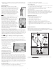
Backup Installation
When the power goes out, the PHCC Pro Series AC sump pumps will not operate. For
protection during a power outage, a PHCC Pro Series battery backup system can be installed.
There are three systems with matching batteries that will provide protection. The following
is an example of a typical battery backup installation.
AC
OUTLET
DELUXE
CONTROL UNIT
M
OUNTED ON
WALL
PUMP
WIRE
GATE
VALVE
CHECK
VALVE
FLOAT
WIRE
FLOAT
WIRE
MAIN A/C PUMP
BATTERY
BACKUP PUMP
BATTERY
45º ELBOW
"Y" CONNECTOR
DRAIN TILE
AC power is out
T
he system is operating
9 volt battery low or slide switch is OFF
Pump or float problem
Make sure this controller is plugged into the wall outlet
Check the circuit breaker
Replace 9 volt alkaline battery or move switch to ON
L
ight should be flashing
T
he pump has run continuously for 10 minutes
Refer to the instructions for possible causes
Slide switch to OFF during power failures
to conserve battery energy and silence alarm
Power Failure Alarm
Consider a
Pro Series
Battery Backup
Sump Pump
System
Remote
Connection
N.O.
Common
N.C.
G
lentronics, Inc.
800.991.0466
www.stopflooding.com
deluxe
Controller
Dual Float
Model No. DFC2
On Off
BATTERY
CABLE
AC
OUTLET
BACKUP SYSTEM
CONTROL UNIT
PUMP
WIRE
Visit our website www.stopflooding.com for more information about the PHCC Pro Series
AC pumps and battery backup sump pump products.
DFC2
3