TM TYTAN Inline Water Heater Instruction Manual www.process-technology.com 7010 Lindsay Dr.
TABLE OF CONTENTS: RELATED DOCUMENTS ............................................................................................... 3 INTRODUCTION............................................................................................................. 4 SYSTEM SPECIFICATIONS .......................................................................................... 6 MODEL NUMBER.........................................................................................................
RELATED DOCUMENTS: The following documents are to be used in conjunction with this manual: ANSI/NFPA70 – National Electric Code→, latest edition. To be used to determine appropriate electrical service, wire sizing, routing and protection. SEMI S2 – Semiconductor Equipment Safety Guidelines, latest edition. To be used in conjunction with safe operation, access and decommissioning procedures. OMRON E5CN INSTRUCTION MANUAL – To be used to access features of the E5CN temperature controller.
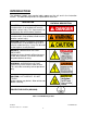
INTRODUCTION: The following symbols and warning labels appear on the unit and in the instruction manual. The table below provides an explanation of each one. DESCRIPTION PICTORAL DESCRIPTION DANGER indicates an imminently hazardous situation which, if not avoided, will result in death or serious injury. This signal word is to be limited to the most extreme situations. WARNING indicates a potentially hazardous situation which, if not avoided, could result in death or serious injury.
INTRODUCTION (Continued): The TYTAN water heater is designed for inline heating of de-ionized (DI) water, city water, reverse-osmosis (RO) water, and filtered seawater. It can perform both as a recirculating heater or a single-pass heater. TEMPERATURE PERFORMANCE: The TYTAN water heater is designed to provide a specified temperature increase at a given flow rate.
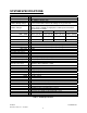
SYSTEM SPECIFICATIONS: Product TYTAN inline titanium water heater Standards UL, cUL standard CE, SEMI S3 optional (-SC) 12kW – 144kW Refer to model number label for the wattage of any specific unit 208V – 600V, 50/60Hz, 3 phase standard (Some voltages available in single phase or with special construction, consult factory for details) Available Wattage Range Available Voltages Cabinet dimensions: Width Depth Height Weight 12kW – 48kW 28.5-in (75 cm) 13.5-in (34 cm) 36-in (91 cm) 145 lbs.
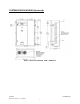
SYSTEM SPECIFICATIONS (Continued): Figure 1: Dimensional Drawing, 12kW – 48kW Units M-45-02 Revision - Date: 01 – 11/16/07 TYTAN Manual 7
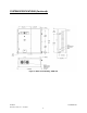
SYSTEM SPECIFICATIONS (Continued): Figure 2: Dimensional Drawing, 72kW Unit M-45-02 Revision - Date: 01 – 11/16/07 TYTAN Manual 8
SYSTEM SPECIFICATIONS (Continued): Figure 3: Dimensional Drawing, 96kW – 144kW Units M-45-02 Revision - Date: 01 – 11/16/07 TYTAN Manual 9
MODEL NUMBER: Process Technology model numbers are designed to offer some description of the heater construction, including features and options. The model number can be found on the model/serial number label located on the front of the unit, near the bottom (see figures 1-3).
Model Number (Continued): Model Number Explanation: Provided below is an example of a typical model number along with an explanation of each part. This key will help you understand your model number. Model number example: TY-072-480-3-SC-RI c d e f g c Heater Series. The beginning of each model number will designate the product line. In this case, the TYTAN inline titanium water heater. d Heater Wattage. The numerical portion of the model number will always begin with the wattage of your heater.
Model Number Explanation (continued): TY-072-480-3-SC-RI c d e f g e Heater Voltage. The first character following the heater Wattage will describe the rated Voltage of the heater. f Heater Phase. This character will specify if this unit is designed for single phase (-1) or three phase (-3) power. g Options. The remaining characters will specify any options included in this system. Many of these options can be combined on a single Tytan water heater. Only a few options are mutually exclusive.
FACILITY REQUIREMENTS: Before installing the TYTAN inline water heater confirm the facility requirements listed below. Space Requirements: The TYTAN inline water heater is constructed in a wall-mounted or freestanding enclosure. The dimensions of this enclosure are based upon the wattage of the unit. This enclosure includes the common framework for the heating column(s) as well as the electrical components. The enclosure requires adequate ventilation.
Facility Requirements (continued): Water Plumbing Requirements: The customer supplied inlet and outlet plumbing must be rated to withstand temperatures up to 275°F (135°C) at pressures up to 100 psi (6.9 Bar). The wall-mounted TYTAN units are supplied standard with 1-inch MNPT threaded pipe connections for the plumbing inlet and outlet. These connections extend from the right side of the unit, with the inlet near the bottom and the outlet near the top (see figures 12).
INSTALLATION: NOTE: The mounting and installation of this unit should only be performed by qualified personnel. Inspection and Uncrating: The wall-mounted TYTAN units are shipped in a horizontal position. The free-standing TYTAN units are shipped in a vertical position. Due to the weight of the unit, DO NOT ATTEMPT to move or lift the unit without the appropriate material handling equipment. 1) Inspect the shipping crate for evidence of damage. If any damage is detected, contact the carrier immediately.
INSTALLATION (Continued): Uncrating the wall-mounted units: 3) Remove the top of the crate. 4) Remove any protective packaging material and any other materials that may have been packed in the crate with the enclosure. 5) Remove any braces used to hold the unit in place during shipping. 6) Using a hoist or other suitable lifting device, lift the unit from the mounting holes on the side flanges and remove from the crate.
INSTALLATION (Continued): Positioning and Mounting: Wall-mounted units: The wall-mounted TYTAN units must be anchored to a support structure that can support at least 275-pounds (125 kg). We recommend that the mounting bolts are no smaller than a 3/8-16 thread. We recommend that the unit is mounted such that the temperature controller is no more than 78-inches (2 meters) above the floor level (see figure 5).
INSTALLATION (Continued): Plumbing: The plumbing installation of this unit should only be performed by qualified technicians. Verify that the water supply is shut off, and any necessary lockout/tagout devices are properly installed. The customer supplied inlet and outlet plumbing must be rated for temperatures up to 275°F (135°C) at pressures up to 100 psi (6.9 Bar). On all TYTAN units, the lower plumbing connection will always be the inlet, and the upper plumbing connections will always by the outlet.
INSTALLATION (Continued): Plumbing (Continued): When tightening all connections on this unit, be sure to support the TYTAN heater connection to prevent excessive torque or strain from damaging the internal plumbing of the unit. Figure 7: Tytan Heater Connection Support Failure to properly support the TYTAN plumbing connections during tightening will result in equipment damage and internal water leaks. Such damage is not covered under the product warranty.
INSTALLATION (Continued): Plumbing (Continued): PRV Plumbing Connection: 1) Test fit the drain pipe to insure proper length. The PRV must be connected to a nonpressurized drain. 2) Support the TYTAN PRV fitting to avoid any damage during tightening. 3) Tighten the connection as required. Take care not to over-tighten. Wiring: The wiring of this unit should only be performed by qualified technicians.
INSTALLATION (Continued): Wiring: 2) Remove front cover of the control side of the cabinet by loosening the cover mounting screws. 3) Cut a hole in the top of the enclosure for the incoming power supply to allow for the power supply to enter the top of the enclosure. 4) Fuse the incoming line for the rated amperage using an approved electrical disconnect box.
INSTALLATION (Continued): Wiring: RC1 (RS232), RC2 (RS485) Options: Serial Communication Interface: Figure 10: Location of optional interface connections In units supplied with the RC1 (RS485) or RC2 (RS232) options, the Omron E5CK temperature controller is equipped with RS-232 / RS-485 Serial Communication capability for use with a customer-supplied host computer. If this option is used, all temperature and related parameters can be monitored or altered from the host computer.
INSTALLATION (Continued): Wiring: RC3 (4-20 mA) Option: Process Output: Units provided with the RC3 option will include a 4-pin connector plug, for wiring of the 4-20 mA process output. This process output will allow the user to record the outlet temperature of the Tytan heater from a remote device. This signal is an output only.
INSTALLATION (Continued): Wiring: RC3 option process output pin assignment: Pin Number 1, 2 Signal EMO Signal type Description The customer supplied remote controller can trip an EMO condition on the unit by opening contacts across these two pins. Input, This is one of the signals that has been bypassed at the factory. In order to use this remote EMO feature, the red tag jumper must be removed. Dry contacts The EMO condition must be reset at the unit.
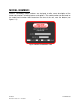
OPERATIONS: Control Panel: Figure 14: Temperature Controller and Control Panel. The TYTAN Heating System incorporates a self-tuning, PID microprocessor based, digital temperature controller with a set high temperature alarm. The PID feature enhances the controller's ability to reach and maintain a constant process temperature. The self-tuning feature enables the controller to measure the process characteristics and indicate desired values, which can be displayed on LED displays.
OPERATIONS (Continued): Temperature Controller E5CN: This section contains information for the E5CN controller only. Do not use these instructions for any other temperature controller, or controller damage may result. Figure 15: Omron Temperature Controller DISPLAY FEATURES: No. 1 display (PV): Shows the process value (outlet temperature), modes and parameter symbols. No. 2 display (SV): Shows set points, parameter operation read value, or the variable input value.
OPERATIONS for E5CN (Continued): Display Symbols: Operation Indicators: ALM1: Illuminates when the alarm 1 setting is ON (tripped) (120°C). ALM2: Illuminates when the alarm 2 setting is ON (tripped) (110°C). ALM3: Not available on this controller. HA: Not available on this controller. OUT1: Illuminates when the control output 1 is ON. OUT2: Illuminates when control output 2 is ON (Not used). STOP: Illuminates when the control operation has stopped.
OPERATIONS for E5CN (Continued): Using the keys: This section describes the basic functions of the front panel keys. Level Key: Press this key to move between setting levels. The setting level is selected in the following order: operation level: adjustment level, initial setting level, communications setting level. Mode Key: Press this key to change parameters within a setting level. The parameters can be reversed by holding down the key (moving one per second in reverse order).
OPERATIONS for E5CN (Continued): Mode Parameter Settings: The Omron E5CN temperature controller has been programmed prior to shipment, so no additional programming is normally necessary. The table below shows the various controller settings for this unit when properly configured to operate the TYTAN inline heater. Some internal menus have been factory programmed and subsequently locked. Those menus are not listed.
OPERATIONS for E5CN (Continued): Changing Primary Set Point: 1. The process Set Point can be changed in the normal display mode. 2. Press the up and down arrow keys to select the desired setting. After changing the process set point (SP-0) on the Omron controller, you must manually adjust the SP2 setting on the Future Design over-temperature control. See OPERATIONS Over-Temperature Controller FDC-L91 section.
OPERATIONS for E5CN (Continued): PID Tuning: The Omron E5CN temperature controller incorporates the capability of automatically tuning the PID parameters (Auto-Tuning) to fit the characteristics of the process. The optimum PID parameters are automatically set by forcibly changing the Manipulated Variable (MV) to calculate the characteristics (limit cycle method) of the control target.
OPERATIONS for E5CK: Temperature Controller E5CK: This section contains information for the E5CK controller only. Do not use these instructions for any other temperature controller, or controller damage may result. The Omron E5CK temperature controller is used on Tytan heaters that utilize the RC1, RC2 or RC3 options. For units with these options, refer to this section (E5CK controller). Do NOT use the section for the E5CN controller Figure 17: Omron Temperature Controller DISPLAY FEATURES: No.
OPERATIONS for E5CK (Continued): A/M key: Switches the controller between auto and manual operation. Display key: Allows selection of the mode when depressed for more than 1 second. Switches parameters when depressed for less than one second. Up and Down arrow keys: Advances, increases or decreases the setting or values in the No. 2 display. OUT1: Illuminates when the controller’s heat output is ON. OUT2: Illuminates when the alarm 1 setting is ON (tripped).
OPERATIONS for E5CK (Continued): Selecting Modes: The modes are selected by pressing the Display Key for one second or greater. The up and down arrow keys allow the movement between modes in the top display.
OPERATIONS for E5CK (Continued): Mode Parameter Settings: The Omron E5CK temperature controller has been programmed prior to shipment, so no additional programming is normally necessary. The table below shows the various controller settings for this unit when properly configured to operate the TYTAN inline heater. Some internal menus have been factory programmed and subsequently locked. Those menus are not listed.
OPERATIONS for E5CK (Continued): Changing Primary Set Point: 3. The process Set Point can be changed in the level 1 mode menu. 4. Press the Display Key for a minimum of one second to enter the level select mode. 5. Press the up or down arrow key to select the desired level. (Level 1 for process set point adjustment). 6. Press the Display Key for a minimum of one second to enter the selected level mode menu. 7.
OPERATIONS for E5CK (Continued): High Alarm: The Digital Temperature Controller incorporates an independent alarm. The High Process Temperature Alarm (AL-1) prevents heater operation above a preset maximum temperature that may harm the process and potentially the tank material. If the process temperature exceeds the preset high alarm value, the heater will be disengaged. The temperature controller will activate once the process temperature exceeds the set point by the preset value.
OPERATIONS for E5CK (Continued): PID Tuning: The Digital Temperature Controller incorporates the capability of automatically tuning the PID parameters (Auto-Tuning) to fit the characteristics of the process. The optimum PID parameters are automatically set by forcibly changing the Manipulated Variable (MV) to calculate the characteristics (limit cycle method) of the control target.
OPERATIONS (Continued): Over-Temperature Controller FDC-L91: 1. This over-temperature controller is located inside the electrical portion of the Tytan heater. It uses a separate temperature sensor to monitor the temperature on the surface of the heating elements. 2. This controller has two discreet set points: SP2: This is the over-temperature cutoff setting, which is set for 18°F (10°C) ABOVE the primary set point on the Process temperature controller.
OPERATIONS (Continued): Mode Parameter Settings: The Futuredesign FDC-L91 temperature controller has been programmed prior to shipment, so no programming will be necessary. The table below shows the various controller settings for this unit when properly configured to operate the TYTAN inline heater. Parameter Description Default Setting HSP1 LSP1 SP2 Hi Limit Set Point Low Limit Set Point Set Point 2 value, for Output 2 INPT UNIT RESO IN.LO IN.HI SHlF FILT OUT1 O1.HY HSP.L HSP.H LSP.L LSP.
OPERATIONS (Continued): Programming FDC-L91: Every time the primary set point of the main controller E5CN is modified, the SP2 setting on the over-temperature controller FDC-L91 must be changed manually. To Change the SP2 set point on the FDC-L91 over-temperature controller, follow the following procedure: Do not change any of the other settings in this controller. 1. Turn the “Enable Heater” switch to the Off position. Leave the “Control Power” switch in the On position. 2.
OPERATIONS (Continued): System Start-Up: 1) Turn on water at its supply source. Allow water to flow for several minutes to insure that all entrapped air has been purged from the heating column(s). 2) Stop water flow at point of use location and check all plumbing connections and water heater for leaks. Repair any water leaks if applicable. 3) Enable the power at the MAIN SERVICE DISCONNECT (provided by customer).
MAINTENANCE: The Tytan water heater requires only a routine inspection every 6 months to check the operation of the various operation and safety devices. Many of these devices require the control system to remain operational during inspection, while others may be checked while the unit is completely powered down. Note: Several maintenance tasks can be completed simultaneously while the cabinet access covers are open and lockout/tagout procedures are in place.
WARRANTY: All PROCESS TECHNOLOGY equipment, heaters and controls have been carefully inspected before shipping and are warranted to be free from defects in workmanship and materials for a period of one year from date of purchase on a pro-rated basis. At its option, PROCESS TECHNOLOGY will repair or replace any defects that are exhibited under proper and normal use.