SFE24RE13-O/C SFE24RE-C/O/CG SFE24REC-C/O/CG SFE24RE6-CG/O/C/W SFE32RE-C/O/CG/W SFE32RE1-C/O/CG/W SFE24RE6 SHOWN Installation Instructions and Owner’s Manual WARNING! IF THE INFORMATION IN THIS MANUAL IS NOT FOLLOWED EXACTLY, A FIRE MAY RESULT CAUSING PROPERTY, PERSONAL INJURY OR LOSS OF LIFE. FOR YOUR SAFETY DO NOT STORE OR USE GASOLINE OR OTHER FLAMMABLE VAPORS OR LIQUIDS IN THE VICINITY OF THIS OR ANY OTHER APPLIANCE ANSI/UL1278.
TABLE OF CONTENTS PLEASE READ THE INSTALLATION & OPERATION INSTRUCTIONS BEFORE USING THIS APPLIANCE IMPORTANT: Read all instructions and warnings carefully before starting installation. Failure to follow these instructions may result in a possible electric shock, fire hazard and will void the warranty. Important Instructions ….…………………………………………………………....2 Locating Your Electric Fireplace…………………………………….………….......3 Clearance To Combustibles………………………………………….…………......3 Electrical Connections…..
IMPORTANT INSTRUCTIONS 11. To disconnect heater, turn controls to OFF, then When using electrical appliances, basic precautions remove plug from outlet. should always be followed to reduce the risk of fire, electric shock, and injury to persons, including the 12. Connect to properly grounded outlets only. following: 13. When this appliance is installed, it must be electri- 1. Read all instructions before using this heater. cally grounded in accordance with local codes with 2.
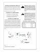
LOCATING YOUR ELECTRIC FIREPLACE Your new freestanding electric fireplace may be installed virtually anywhere in your home. However when choosing a location for your new electric fireplace, ensure that the general instructions are followed. For best effect results, install the electric fireplace out of direct sunlight. CLEARANCE TO COMBUSTIBLES This fireplace is a zero-clearance design. The fireplace can set flush (0mm,0inches) to combustibles on floor,wall and top.
MAINTENANCE OF MOTORS GLASS INFORMATION The motors used on the fan and flame genera- 1.Do not use fireplace if glass is missing or broken. tor assembly are prelubricated for extended 2. Do not strike or slam the glass. bearing life and require no further lubrication. 3. Do not use abrasive cleaners to clean the glass. However, periodic cleaning/vacuuming of the 4. Replacement glass is available from the manufacturer and replacement should be carried out fan/heater unit is recommended.
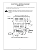
ELECTRICAL WIRING DIAGRAM (SFE24 Series) Any electrical repairs or rewiring of this unit should be carried out by a licensed electrician in accordance with national and local codes. WARNING: If repairing or replacing any electrical component or wiring, the original wire routing, color coding and securing location must be followed.
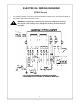
ELECTRICAL WIRING DIAGRAM (SFE32 Series) Any electrical repairs or rewiring of this unit should be carried out by a licensed electrician in accordance with national and local codes. WARNING: If repairing or replacing any electrical component or wiring, the original wire routing, color coding and securing location must be followed.
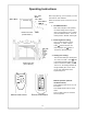
Operating Instructions Before programming your transmitter you must first insert two “AAA” batteries. Make sure the main power on/off switch is “ON” position. 1. The ON/OFF button: *Note: When Fireplace is first operated, the default setting will be: brightest flame, and full heating To turn on Heater, press the “ON/OFF” button. To turn off heater,press the “ON/OFF” button again. Heater Front View (SFE24 Series ) 2.
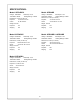
SPECIFICATIONS: Model: SFE24RE13 Model: SFE24RE Voltage: 120V/60HZ Voltage: 120V/60HZ Total Amps: 11.5A Total Watts: 1380W Total Watts: 1380W Heating Ratings: 1200W Total Amps: 11.
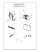
Replacement Parts (SFE24RE13-O/C Series) 14 190
Replacement Parts List (SFE24RE13-O/C Series) Item Part Description Part Number SFE24RE13-O/C FE23A402 1 Log As s em bly FE24M403 FE24M404 FE24M405 2 Control Box ECRMB3 3 Receiver ECRRA1 4 Fan Heater As s em bly GL45.
Replacement Parts (SFE24RE6-C/CG/O/W Series) 14 112 1
Replacement Parts List (SFE24RE6-C/CG/O/W Series) Part Num ber Item Part Description SFE24RE6-C/CG/O/W FE23A402 1 FE24M403 Log As s em bly FE24M404 FE24M405 2 C ontrol Box EC R MB3 3 R eceiver EC R R A1 4 Fan H eater As s em bly GL45.
Replacement Parts (SFE24RE-O/C/CG Series) 14 131 4
Replacement Parts List (SFE24RE-O/C/CG Series) Part Number Item Part Description SFE24RE-O/C/CG FE23A402 1 FE24M403 Log As s em bly FE24M404 FE24M405 2 Control Box ECRMB3 3 Receiver ECRRA1 4 Fan Heater As s em bly GL45.
Replacement Parts (SFE24REC-C/O/CG Series) 14 15 11 16
Replacement Parts List (SFE24REC-O/C/CG Series) Part Number Item Part Description SFE24REC-O/C/CG FE23A402 1 FE24M403 Log Assembly FE24M404 FE24M405 2 Control Box ECRMB3 3 Receiver ECRRA1 4 Fan Heater Assembly GL45.
Replacement Parts (SFE32RE1-C/CG/O/W Series) 171 8 12
Replacement Parts ( SFE32RE1-C/CG/O/W Series) Item Part Number Part Description SFE32RE1-C/CG/O/W 1 Mantel Front FE32RE1-502-X* 2 Mantel Top FE32RE1-501-X* 3 Mantel Bas e FE32RE1-505-X* 4 Mantel Side FE32RE1-503-X* 5a Door (Left) FE32A152 L 5b Door (Right) FE32A152 R 6 Fan Heater As s em bly GL45.
Replacement Parts (SFE32RE-C/CG/O/W Series) 20 19
Replacement Parts ( SFE32RE-C/CG/O/W Series) Part Number Item Part Description SFE32RE-C/CG/O/W 1 Mantel Front FE32RE-502-X* 2 Mantel Top FE32RE1-501-X* 3 Mantel Base FE32RE1-505-X* 4 Mantel Side FE32RE1-503-X* 5a Door (Left) FE32A152 L 5b Door (Right) FE32A152 R 6 Fan Heater Assembly GL45.
INSTALLATION INSTRUCTIONS For CORNER SURROUND AND HEARTH READ INSTRUCTIONS BEFORE BEGINNING INSTALLATION. Check to see that you have the following. If any part or parts are missing, contact the dealer where you bought the surround and hearth. TOOLS REQUIRED: Measuring Tape, Pencil, Level, #2 Phillips Screw Driver, Hammer, Electric Drill, 5/6" Drill Bit, Hand or Electric Saw INSTALLATION: 1. Surround must be installed flush with wall. Baseboards will prevent proper installation of surround.
6. Place the assembled fireplace on the middle where it is 27” from the corner and form a 45 degree angle to each side wall. Move the assembled surround to the corner, with side panels close to side walls. Move the fireplace to where it can properly attach the surround. 7. Turn up the back of mantel top, the special spring will lock the rear mantel top in position, then use 14 screws to secure bracket as show in Figure 5 make sure the front and rear mantel top are in the same level. 8.