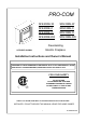
PRO-COM SFE23RE-W SFE23RE-C SFE23RE-O SFE33RE-W SFE33RE-C SFE33RE-O SFE23RE-DO SFE33RE-DO Freestanding Electric Fireplace SFE23RE SHOWN Installation Instructions and Owner’s Manual WARNING! IF THE INFORMATION IN THIS MANUAL IS NOT FOLLOWED EXACTLY, A FIRE MAY RESULT CAUSING PROPERTY, PERSONAL INJURY OR LOSS OF LIFE. FOR YOUR SAFETY DO NOT STORE OR USE GASOLINE OR OTHER FLAMMABLE VAPORS OR LIQUIDS IN THE VICINITY OF THIS OR ANY OTHER APPLIANCE ANSI/UL1278.
TABLE OF CONTENTS PLEASE READ THE INSTALLATION & OPERATION INSTRUCTIONS BEFORE USING THIS APPLIANCE WE ARE PLEASED THAT YOU HAVE CHOSEN TO PURCHASE AN ELECTRIC FIREPLACE MANUFACTURED BY NANJING PRO-COM ELECTRIC APPLIANCE CO., LTD IMPORTANT: Read all instructions and warnings carefully before starting installation. Failure to follow these instructions may result in a possible electric shock, fire hazard and will void the warranty. Important Instructions ….…………………………………………………………....
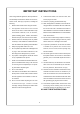
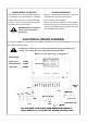
IMPORTANT INSTRUCTIONS 11. To disconnect heater, turn controls to OFF, then When using electrical appliances, basic precautions remove plug from outlet. should always be followed to reduce the risk of fire, electric shock, and injury to persons, including the 12. Connect to properly grounded outlets only. following: 13. When this appliance is installed, it must be electri- 1. Read all instructions before using this heater. cally grounded in accordance with local codes with 2.
LOCATING YOUR ELECTRIC FIREPLACE WARNING: Electrical outlet wir- Your new freestanding electric fireplace may be installed vir- ing must comply with local build- tually anywhere in your home. However when choosing a ing codes and all other appliable location for your new electric fireplace, ensure that the gen- regulations to reduce the risk of eral instructions are followed. For best effect results, install fire, electrical shock and injury. the electric fireplace out of direct sunlight.
MAINTENANCE OF MOTORS GLASS INFORMATION The motors used on the fan and flame genera- 1. Under no circumstances should this product be operated with missing or broken glass. tor assembly are prelubricated for extended bearing life and require no further lubrication. 2. Do not strike or slam the glass. However, periodic cleaning/vacuuming of the 3. Do not use abrasive cleaners to clean the glass. fan/heater unit is recommended. 4.
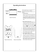
Operating Instructions Before programming your transmitter you must first insert three triple “AAA” batteries. Make sure the main power on/off swith is in “ON” position. 1. The Mode setting: Press the “SET” button, then the “AUTO” light will flash. Press the “SET” button again, and then the “MANUAL” light will also flash. The “AUTO” light and the “MANUAL” light will flash alternately and continuously. Next press “ENTER” button to select the auto mode or manual mode. Heater Front View a.
2. The Clock setting : Press the “CLOCK” button, the figure shown on clock will flash. Press or to set the hour. After the hour has been set, press the “CLOCK” button again to set the minutes. After the minutes has been set, press the “CLOCK” button, the clock will indicate the set time. 3. The Timer setting : Press the “TIMER” button, the word “TIMER” will appear on the transmitter, next press or to adjust the time, to add 30 minutes increments press the button again.
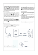
SPECIFICATIONS: Model: SFE33RE-W (-C, -O, -DO) Voltage: 120V/60HZ Total Amps: 11.5A Total Watts: 1380W Heating Ratings: 1200W Dimensions, Inches (H x W X D) Model: SFE23RE-W (-C, -O, -DO) Voltage: 120V/60HZ Total Amps: 11.
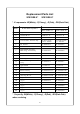
Replacement Parts List SFE23RE-X* SFE33RE-X* * -X represents -W(White), -C(Cherry), -O(Oak), -DO(Dark Oak) It e m P a rt N u m b e r P a r t D e s c r ip t io n S F E 2 3 R E -X * S F E 3 3 R E -X * 1 Log Set FE23A 400 FE33A400 2 C o n tr o l B o x N A E Y1 1 -A N A E Y1 1 -A 3 R e c e ive r N A E Y1 1 -C S N A E Y1 1 -C S 4 F a n H e a te r A s s e m b ly N F H TX 186 / V B 1 7 -0 0 0 G N F H T X 1 8 6 /V B 1 7 -0 0 0 G 5 D C M o to r FE23A 304 FE23A304 6 P o w e r C o r d w /Te
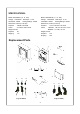
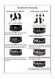
Installing decorating logs Installing logs for SFE23RE: Installing logs for SFE33RE: 2 1 1 3 3 2 FIG 1 - Logs for SFE23RE 4 5 6 FIG 5 - Logs for SFE33RE 1 1 2 3 FIG 2 1.Insert the two pins on log 1 to the two recessed holes at the middle of grate. (See FIG 2). 2 FIG 6 1.Place log 1, log 2 and log 3 into the corresponding holes on grate. (See FIG 6). 1 4 1 FIG 3 3 FIG 7 2.