
User Manual

8
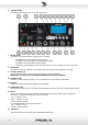
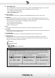
6. CONTROL PANEL
Through the control panel you can operate the system.
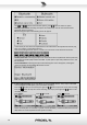
7. BATTERY LEVEL
This LED bar indicates the battery charging status as follows:
- 100 GREEN: the internal battery is fully charged.
- 75 GREEN: the internal battery is three/quarter charged.
- 50 GREEN: the internal battery is half charged.
- 25 RED: the internal battery is near to be exhausted, you must re-charge it as soon as possible.
8. CHARGE LED
This LED in on when the FREE5LT is connected to the mains and the internal battery is charging.
9. DC INPUT 16VDC/1.5A
This is the input where to connect the AC/DC adaptor to power the FREE5LT.
IMPORTANT: USE ONLY THE AC/DC ADAPTOR INCLUDED IN THE FREE5LT PACKAGE.
10. ALARM BUTTON
This button, when pressed, activates a siren sound (all other sound sources are disabled).
11. PWR LED
The green LED lights up when the FREE5LT is switched ON.
12. POWER/MIC LEVEL
This control has a dual function: it switches ON the FREE5LT and it sets the level of the MIC IN jack input.
13. MIC IN
This is a female jack connector that accepts a JACK plug from any dynamic balanced or unbalanced
microphone. The balanced JACK input is wired as follows:
Tip = + positive or "hot"
Ring = - negative or "cold"
Sleeve = shield or ground
The unbalanced JACK input is wired as follows:
Tip = + positive or "hot"
Sleeve = shield or ground
14. LINE LEVEL
This potentiometer sets the level of the LINE IN MINI JACK input.