OMRON Corporation CS/CJ Series PLC Ladder Monitor Operation Manual
Introduction Thank you for purchasing the PLC Ladder Monitor Add-on Kit for the OMRON Corporation CS/CJ Series. This manual explains the operation for monitoring the ladder programs of the external device and device addresses using the GP3000 Series programmable Display manufactured by Pro-face (Digital Electronics Corporation). Please read the manual thoroughly for proper use of this product. Be sure the manual is always available where this product is used.
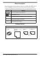
Manual Description This manual provides following cautions for proper use of the PLC Ladder Monitor Add-on Kit for the OMRON Corporation CS/CJ Series. The cautions described herein contain important safety informaiton. The following table shows the symbols and what they mean. Symbol Meaning Failure to follow the instructions on the display may result in adverse events such as device errors or data loss. Important points for use. * The footnotes contain an explanation of the annotated words.
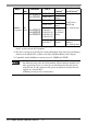
Supported Models Supporting External Devices Maker Series Name Connection Method*1 Driver Name on GPPro EX (Version)*2 RS232C port on the CPU unit Peripheral port RS-232C or on the CPU RS-422/485 unit (4wire) CS1W-SCU21 CS1W-SCU21-V1 CS1W-SCB21 CS1W-SCB41 CS/CJ series HOST link (V1.13.02 or later) CS1W-ETN01 CS1W-ETN11 Ethernet CS1W-ETN21*3 CS/CJ Series Ethernet (V1.14.
Maker Series Name CPU Model Link I/F CP1W-CIF01 CP1L-MD- CP1L-LD- CP1W-CIF11 CP1W-CIF01 CP1W-CIF11 OMRON CP1 Corporation Series CP1H-XD- CP1H-XAD- CP1H-YD- Connection Method*1 RS-232C RS-422/485 (4wire) RS-232C RS-422/485 (4wire) CJ1W-SCU41 CJ1W-SCU21 RS-232C or CJ1W-SCU41-V1 RS-422/485 CJ1W-SCU31-V1 (4wire) CJ1W-SCU21-V1 CJ1W-ETN21*3 Ethernet Driver Name on GPPro EX (Version)*2 CS/CJ Series HOST link (V1.13.02 or later) CS/CJ Series Ethernet (V1.14.
Relevant Display Displays that support the ladder monitor are GP3000 Series models with VGA, SVGA, and XVGA resolution. For details on supported models, see the table below.
PLC Ladder Monitor Operation Manual 6
Table of Contents Introduction ............................................................................................................................................ 1 Manual Description ................................................................................................................................ 2 Package Content .................................................................................................................................... 2 Supported Models ....................
PLC Ladder Monitor Operation Manual 8
1 Summary 1.1 Ladder Monitor ................................................................................................1-2 1.2 System Configuration......................................................................................1-3 1.3 Installation Procedure .....................................................................................
Ladder Monitor 1.1 Ladder Monitor The ladder monitor is a feature that reads and monitors the external device (OMRON Corporation PLC CS/CJ series) ladder programs on a display screen. It monitors the ladder programs online without stopping other features. Production Input Screen 7 8 9 4 5 6 1 2 3 0 .
System Configuration 1.2 System Configuration • For details regarding the connection of display devices and external devices, refer to “CS/CJ Series HOST Link Drivers” or “CS/CJ Series Ethernet Drivers” in the “GP-Pro EX Device Connection Manual.” Communication Cable Connection Display device units: Displays the connection status through the external device units. • The display and external device are connected 1:1 with a connection cable.
System Configuration • 1-to-1 connection (Ethernet connection) CS1 series Display Connection cable HUB • 1-to-n connection (When accessing the Ethernet connection by surpassing the network.
System Configuration • n-to-1 connection (Ethernet connection) Display Display Display External device HUB • n-to-m connection (Ethernet connection) Display Display Display HUB External device External device External device Up to 32 units • Through Ladder Monitor functions, the supported Ethernet transfer protocols are TCP/IP and UDP/IP.
Installation Procedure 1.3 Installation Procedure 1 Install the add-on kit ) “2.2.2 Setup Procedure” (page 2-4) 2 Install the startup file onto a CF Card ) “2.2.2 Setup Procedure” (page 2-4) 3 Create a project file See: 4 Configure the device monitor ) “2.2.2 Setup Procedure” (page 2-4) 5 Transfer the project file with the device monitor settings to the display See: GP-Pro EX Reference Manual GP-Pro EX Reference Manual 6 Convert comment file See: “Start up procedure from the 2.2.
2 Using the Ladder Monitor 2.1 Settings Menu .................................................................................................2-2 2.2 Monitoring the Ladder Programs of the External Device on a Display............2-3 2.3 Displaying Ladder Programs in Alarm History View...................................... 2-11 2.4 Printing the Ladder Monitor View from a Display ..........................................2-13 2.5 Capturing and Saving the Ladder Monitor View on a CF Card ............
Settings Menu 2.1 Settings Menu Monitoring the Ladder Programs of the External Device on a Display ) “2.2.1 Details” (page 2-3) ) “2.2.2 Setup Procedure” (page 2-4) CF Card You can display the ladder program of the external device on a display screen.
Monitoring the Ladder Programs of the External Device on a Display 2.2 Monitoring the Ladder Programs of the External Device on a Display 2.2.1 Details • See the following pages for the detailed settings. )Chapter3 "Ladder Monitor Screen Features" (page 3-1) With the Ladder Monitor you can remotely view, search, and edit the ladder program of the external device as it appears on the HMI. CF Card • The CF Card must have 256 MB or more of free space. • See the following pages for the search feature.
Monitoring the Ladder Programs of the External Device on a Display 2.2.2 Setup Procedure 1 Install the Ladder Monitor CD-ROM onto a PC installed with GP-Pro EX. Run Setup.exe on the CD to launch the installer. Follow the installer instructions to install. • Your PC must have GP-Pro EX Ver.2.00 or later installed. For the OS, see the GP-Pro EX Reference Manual. 2 Install the startup file on a CF Card. • To use this feature, the CF Card must have 256 MB or more of free space.
Monitoring the Ladder Programs of the External Device on a Display Start up procedure from switch parts Production Input Screen 7 8 9 4 5 6 1 2 3 E N 0 . T Ladder Monitor 1) From the [Parts (P)] menu, point to [Switch Lamp (C)] and select [Special Switch (P)] or click . Click and drag to place a switch is placed on the screen. 2) Double-click the switch you placed and in [Special Action] select [Start monitor switch]. In [Action], select [Ladder Monitor] or [Ladder Monitor (Cache)].
Monitoring the Ladder Programs of the External Device on a Display • Read the cache from a CF Card Normally, every time you start the Ladder Monitor, it communicates with the PLC to read the ladder programs and it may take time to display the ladder programs. To improve the display update speed, the Ladder Monitor feature reads the ladder programs of the external device onto the device CF Card (cache) first and then displays them.
Monitoring the Ladder Programs of the External Device on a Display Start up procedure from the LS area The Ladder Monitor starts up if you turn ON bits in the LS area. Configure the settings for turning ON the following bits using switch parts and D-scripts. 15 3 2 1 LS2078 Reserved Reserved 1: Starting up the Ladder Monitor Reserved 1: Reading the cache data Bit 1 Turn ON to start up the Ladder Monitor. Turn ON to start the Ladder Monitor and display the ladder programs cached on the CF Card.
Monitoring the Ladder Programs of the External Device on a Display 4 Register the device monitor feature. In GP-Pro EX, from [System Settings], point to [Display Unit] and select [Extended Settings]. Select the [Device Monitor] checkbox. • The device monitor screen uses a global display window. While the device monitor is displayed, the screen cannot display other global windows. When you select the [Device Monitor] checkbox, [Global Window] operation is automatically set to [Indirect].
Monitoring the Ladder Programs of the External Device on a Display 7 Install the CF Card onto the GP. Reference: For details on installing a CF Card, see “GP3000 Series Hardware Manual”. 8 Connect the display to communicate with the external device. Reference: For details on the connection, see “GP-Pro EX Device Connection Manual” 9 Start up the Ladder Monitor. There are four ways to start up the Ladder Monitor.
Monitoring the Ladder Programs of the External Device on a Display 10 When the ladder monitor starts up, the Device/PLC Selection screen is displayed. Select the external device for the ladder program you wish to monitor. The screen jumps to the File Selection screen. • For the File Selection screen, see the following pages. ) “3.
Displaying Ladder Programs in Alarm History View 2.3 Displaying Ladder Programs in Alarm History View 2.3.1 Details Place the Ladder Monitor startup switch on the alarm history screen. This allows you to display the device whose the alarm is sounding directly from the history screen.
Displaying Ladder Programs in Alarm History View 3 After reading is complete, the device search keypad will be displayed The device address you selected on the alarm history screen is automatically entered. Touch [Search] • Select the appropriate external device and read it. After reading is completed the device search keypad is displayed. 4 The ladder programs will be displayed starting with the device for which the alarm sounded. • The previously read ladder program is displayed again.
Printing the Ladder Monitor View from a Display 2.4 Printing the Ladder Monitor View from a Display 2.4.1 Details You can output the Ladder Monitor screen from a printer connected to the display. This allows you to efficiently save and analyze data. 2.4.2 Setup Procedure 1 Connect the display to the printer. Reference: GP-Pro EX Reference Manual 2 On the Ladder Monitor main screen, touch [Print].
Capturing and Saving the Ladder Monitor View on a CF Card 2.5 Capturing and Saving the Ladder Monitor View on a CF Card 2.5.1 Details You can capture and save the Ladder Monitor screen on a CF Card. This allows you to efficiently save and analyze data. CF Card 2.5.2 Setup Procedure 1 On the Ladder Monitor main screen, touch [Capture]. Illuminated in red during capturing 2 The currently displayed screen is captured.
3 Ladder Monitor Screen Features 3.1 Main Screen ....................................................................................................3-2 3.2 File Selection Screen ......................................................................................3-6 3.3 Menu Screen...................................................................................................
Main Screen 3.1 Main Screen Names and Features on the Main Screen Step number Current Value I/O comments Power bar Error display Setting/Notated Items Menu Read Power bar Setting/Notated Contents This displays the menu screen. For details, see the following pages. ) “3.3 Menu Screen” (page 3-8) This displays the file selection screen where you select the ladder program to read. For details, see the following pages. ) “3.
Main Screen Setting/Notated Items Setting/Notated Contents This switches between decimal, binary-coded decimal, and hexadecimal current values. The switch display changes between [Decimal] and [Hexadecimal] every time it is touched. Unsigned decimal/ Signed decimal/ Hexadecimal • Ccurrent values are displayed in the following two ways: Contact/Coil Displays energized/non-energized state by the thickness of parts lines. An energized state is displayed in bold lines.
Main Screen Setting/Notated Items Setting/Notated Contents This selects the display method for I/O comments. Touch to switch Short Comment Mode --> Compressed Comment Mode -> No Comment Mode in this order. • Short comment mode This displays up to 5 single-byte characters x 3 lines of comments. • Compressed comment mode This displays up to 5 single-byte characters x 3 lines of comments. This displays the characters compressed to 1/2 vertical size. • No comment mode This displays no I/O comments.
Main Screen • The ladder rungs that you can display differ depending on the comment mode.
File Selection Screen 3.2 File Selection Screen Names and Features on the File Selection screen Setting Description type This displays the ladder type. CYCLE: Cycle program INTERRUPT: Interrupt program This displays the ladder number. Ladder Files no. program name Comment Files This displays the status of the program property, “Task Reading Protection,” and display the presence or absence of reading protection. * : Protected This displays the list of comment files on the CF card.
File Selection Screen Setting Description This reads the ladder programs onto a CF Card. • The read button triggers saving of only ladder programs and comments to the CF Card. It always reads and displays the latest numeric values from the external device. Reading to a CF Card If you change the ladder programs or comments on the PLC after reading the data of the external device to the CF card of the display, the Ladder Monitor for the display will not be updated.
Menu Screen 3.3 Menu Screen Setting Description This searches by the step number (number of steps) of the ladder program. This displays the ladder program with the specified step number (number of steps) at the top of the screen. Step Search This searches by the device address. This displays the ladder program with the specified device address at the top of the screen. Device Search • When you touch a device on the screen twice, the [Device Search] dialog box will appear.
Menu Screen Setting Description This searches by output instruction. This displays the ladder program with the specified output instruction at the top of the screen. Coil Search Device monitor This displays the device monitor screen. This closes the menu screen and returns to the previously displayed screen. • For the device monitor feature, see the following manual.
Menu Screen PLC Ladder Monitor Operation Manual 3-10
4 Restrictions 4-1
Ladder Monitor Restrictions • Depending on the version, your programming tool may not be able to display ladder programs. For the versions supporting programming tools, see the Pro-face support site “Otasuke Pro!”. For the instructions that you can monitor, see the manual of the external device. • To use this feature, your CF Card must have 256 MB or more of free space. • When reading the ladder program, you cannot read only the comment file.
Error Messages Error Messages Solution Please check if the CF Card is inserted properly. • Please check if the CF Card is inserted properly. It failed to read a file in the CF- • When the ladder program is set as CACHE, it is Card. possible that a cache does not exist on the CF Card. In this case, read the ladder program again. • Please check if the CF Card is inserted properly. • Please check if the CF Card has enough space.
PLC Ladder Monitor Operation Manual 4-4