
Installation Sheet


PROFLO.COM
Distributed Exclusively by Ferguson and Wolseley Canada
© 2018 Ferguson Enterprises, Inc. 0718 892675
2
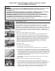
1. Check Flush Cartridge
A. Turn off water supply and flush toilet.
B. Pour water onto top of cartridge (Fig. 1) and turn
on water.
C. Watch for air bubbles. Consistent flow of bubbles
indicates cartridge needs to be replaced. No
bubbles visible, move on to Step 4.
1. Vérification de la cartouche de chasse
A. Fermez le robinet d’alimentation en eau, puis
déclenchez la chasse.
B. Versez de l’eau sur le dessus de la cartouche (fig.
1), puis ouvrez le robinet d’alimentation en eau.
C. Vérifiez si des bulles d’air se forment. Un
écoulement de bulles constant indique que la
cartouche doit être remplacée. Si aucune bulle
n’apparaît, passez à l’étape 4.
1. Compruebe el cartucho de descarga
A. Corte el suministro de agua y descargue el
excusado.
B. V ierta agua encima del cartucho (Fig. 1) y abra el
agua.
C. Vea si hay burbujas de aire. Un flujo constante de
burbujas indica que el cartucho debe sustituirse. Si
no hay burbujas visibles, vaya al Paso 4.
Function: Less than 1.0 gpf/3.8 Lpf
Installation Requirements:
min. 25 psi static water
pressure*
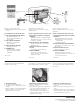
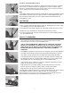
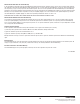
List of Components for 503 and 504 Series:
1. Lower Supply Group w/Hose BL100504-3
(A) Supply Shank w/inlet screen
(B) Pressure Regulator w/Back Check
(C) Relief Valve
2. Upper Supply Group BU100505
(D) Air Inducer Cap w/duckbill
(E) Vacuum Breaker
3. Flush Valve Cartridge Assembly
(F) Actuator w/setscrew
4. FLUSHMATE
®
Tank
(G) Discharge Extension w/Drain
(H) Name Plate w/Serial Number
(I) Flush Rod
*max. 125 psi
Función: Menos de 1.0 gpf/3.8 Lpf
Requisitos de instalación: mín. presión de agua
estática de 25 psi*
Lista de componentes para las series 503 y 504:
1. Grupo inferior de suministro con manguera
BL100504-3
A) Vástago de suministro con pantalla de admisión
(B) Regulador de presión con supresión trasera
(C) Válvula de seguridad
2. Grupo de suministro superior BU100505
(D) Tapa inductora de aire con pico de pato
(E) Divisor de vacío
3. Conjunto del cartucho de la válvula de
descarga
(F) Accionador con tornillo de fijación
4. Tanque FLUSHMATE
®
G) Extensión de descarga con drenaje
(H) Placa de nombre con número de serie
(I) Varilla de descarga
*máx. 125 psi
Fonction: moins de 1,0 gpc/3,8 lpc
Exigences d’installation: 25 psi de pression d’eau
statique min.*
Liste des composants des séries 503 et 504:
1. Groupe d’alimentation inférieur avec flexible
BL100504-3
(A) Tige d’alimentation avec grille d’entrée
(B) Régulateur de pression avec dispositif
antirefoulement
(C) Soupape de décharge
2. Groupe d’alimentation supérieur BU100505
(D) Soupape d’entrée d’air avec bec de canard
(E) Casse-vide
3. Cartouche du robinet de chasse
(F) Actionneur avec vis de pression
4. Réservoir FLUSHMATE
®
(G) Rallonge d’évacuation avec drain
(H) Plaque d’identification avec numéro de série
(I) Levier de déclenchement
*125 psi max.
(F)
❸
❹
(D)
(E)
(I)
(G)
❷
(H)
❶
(A)
(B)
(C)
Installation
Please follow the toilet manufacturer’s installations
instruction for installing the fi xture. Note that the toilet
requires a minimum water supply line pressure of
25 psi for a 1 gpf fi xture. Before attaching, you should
always fl ush the water supply lines.
After completing the installation, you are required to
adjust the Cartridge Actuator (F). To adjust, make sure
the water is turned on and the vessel is completely
charged. The Actuator needs to be set at the proper
clearance, 1/8” from either the Flush Rod or push
button. To make this adjustment, hold the Actuator
while loosening the Phillips setscrew in the center of
the Actuator, and rotate the Actuator up
(counterclockwise) or down (clockwise) until the proper
clearance is obtained. See Figure 1 for cle
arance
required for fl ush-handle fi xture. Tighten setscrew after
adjusting the Actuator.
Additional notes:
• You may be required to initially fl ush the toilet a few
times to properly charge the system.
• Should your fi xture develop a leak between the tank
and bowl, please refer to the fi xture manufacturer’s
installation instructions.
Instalación
Siga las instrucciones de instalación del fabricante del
excusado para instalarlo. Observe que el excusado
requiere un suministro de presión de la línea de agua
para un dispositivo de 25 psi para un dispositivo de 1
gpf. Antes de instalarlo, siempre debe purgar las líneas
de suministro de agua.
Después de fi nalizar la instalación, debe de ajustar el
Accionador del Cartucho (F). Para ajustarlo, asegúrese
d
e que el agua esté activada y la vasija esté totalmente
cargada. El accionador tiene que ajustarse al huelgo
correspondiente, a 1/8” de la varilla de descarga o del
botón. Para hacer este ajuste, sostenga el accionador
mientras afl o j a el tornillo de fi j ación de cruz del centro
del accionador y gire el accionador hacia arriba (en
sentido contrario al de las manecillas del reloj) o hacia
abajo (en el sentido de las manecillas del reloj) hasta
obtener el huelgo correcto. Véase la Figura 1 para
conocer el huelgo necesario para el dispositivo de
manija de descarga. Apriete el tornillo de fi j ación
después de ajustar el accionador.
Notas adicionales:
• Es posible que sea necesario que primero descargue
el excusado varias veces para cargar
adecuadamente el sistema.
•
Si su dispositivo desarrolla una fuga entre el tanque
y la taza, consulte las instrucciones de instalación
del fabricante del dispositivo.
Installation
Veuillez installer l’appareil sanitaire en suivant les
instructions d’installation du fabricant de la toilette.
Prenez note que la pression du tuyau d’alimentation
en eau de la toilette doit être d’au moins pour
un appareil de et d’au moins pour un appareil de 1
gpc. Vous devez toujours évacuer l’eau des tuyaux
d’alimentation en eau avant de les raccorder.
Une fois l’installation terminée, vous devrez régler
l’actionneur de la cartouche (F). Pour le régler,
assurez-vous d’avoir ouvert l’alimentation en eau et
vérifiez que le récipient est complètement rempli.
Pour que l’actionneur soit correctement réglé,
l’
espacement entre celui-ci et le levier de
déclenchement ou le bouton-poussoir doit être de
1/8 po. Pour effectuer ce réglage, tenez l’actionneur
tout en desserrant la vis de pression Phillips au
centre de l’actionneur, puis faites pivoter l’actionneur
vers le haut (sens antihoraire) ou vers le bas (sens
horaire) pour obtenir l’espacement adéquat. La fi g ure
1 montre l’espacement nécessaire pour les appareils
à manette de chasse. Serrez la vis de pression une
fois le réglage de l’actionneur terminé.
Autres remarques:
• Initialement, il est possible que vous deviez
déclencher la chasse de la toilette à plusieurs
reprises afi n de remplir correctement le système.
• En cas de fuite entre le réservoir et
la cuvette,
veuillez consulter les instructions d’installation du
fabricant de l’appareil sanitaire.
-5-
*max. 125 psi *máx. 125 psi
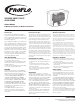
FLUSHMATE
®
504
Function: Less than 1.0 gpf/3.8 Lpf
Installation Requirements: min. 25 psi static water
pressure*
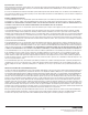
List of Components for 503 and 504 Series:
1. Lower SupplyGroup w/Hose BL100504-3
(A) Supply Shank w/inlet screen
(B) Pressure Regulator w/Back Check
(C) Relief Valve
2. Upper SupplyGroup BU100505
(D) Air Inducer Cap w/duckbill
(E) Vacuum Breaker
3. Flush Valve Cartridge Assembly
(F) Actuator w/setscrew
4. FLUSHMATE
®
Tank
(G) Discharge Extension w/Drain
(H) Name Plate w/Serial Number
(I) Flush Rod
FLUSHMATE
®
504
Función: Menos de 1.0 gpf/3.8 Lpf
Requisitos de instalación: mín. presión de agua estática
de 25 psi*
Lista de componentes para las series 503 y 504:
1. Grupo inferiordesuministro con manguera
BL100504-3
(A) Vástago de suministro con pantalla de admisión
(B) Regulador de presión con supresión trasera
(C) Válvula de seguridad
2. Grupo desuministrosuperior BU100505
(D) Tapa inductora de aire con pico de pato
(E) Divisor de vacío
3. Conjunto del cartucho de la válvula de
descarga
(F) Accionador con tornillo de fijación
4. Tanque FLUSHMATE
®
(G) Extensión de descarga con drenaje
(H) Placa de nombre con número de serie
(I) Varilla de descarga
FLUSHMATE
®
504
Fonction : moins de 1,0 gpc/3,8 lpc
Exigences d’installation : 25 psi de pression d’eau
statique min.*
Liste des composants des séries 503 et 504 :
1. Groupe d’alimentation inférieur avec flexible
BL100504-3
(A) Tige d’alimentation avec grille d’entrée
(B) Régulateur de pression avec dispositif
antirefoulement
(C) Soupape de décharge
2. Groupe d’alimentation supérieur BU100505
(D) Soupape d’entrée d’air avec bec de canard
(E) Casse-vide
3. Cartouche du robinetde chasse
(F) Actionneur avec vis de pression
4. Réservoir FLUSHMATE
®
(G) Rallonge d’évacuation avec drain
(H) Plaque d’identification avec numéro de série
(I) Levier de déclenchement
*125 psi max.
-2-
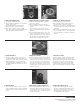
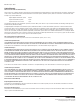
Step 1. Check Flush Cartridge
A. Turn off water supply and flush toilet.
B. Pour water onto top of cartridge (Fig. 1) and turn on water.
C. Watch for air bubbles. Consistent flow of bubbles indicates cartridge needs to be
replaced. No bubbles visible, move on to Step 4.
Step 2. Flush Cartridge Replacement
A. Turn off water and flush the toilet.
B. Use the handle end of pliers (Fig. 2) to unscrew the cartridge from the vessel.
C. Drop in new cartridge and screw in until one female thread (Fig. 3) of vessel
is showing.
D. Turn on water. Continue to screw in cartridge slowly, 1/8 to 1/4 turn increments
until water stops running into the bowl and tank pressurizes.
Step 3. Actuator Adjustment
A. Start by loosening the setscrew in the center of the actuator. Adjust the height of
the actuator by screwing it up or down. There should be a gap (Fig. 4) (about the
thickness of a penny) between the rod and actuator when gently lifting the rod.
When accomplished tighten the setscrew in the center of the actuator.
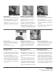
Step 4. Check Air Inducer
A. Place several drops of water over hole on top of air inducer and flush toilet (Fig. 5).
If drop is vacuumed in, move onto step 6. If not, air inducer needs to be cleaned.
Step 5. Clean Air Inducer
A. Turn off water and flush toilet. Unscrew the cap of the air inducer (the smaller of
the two caps) (Fig. 6).
B. Pull the duckbill out from the cap and clean it by gently squeezing it (Fig. 7)
between your fingers under a flow of water. Inspect the lips of the duckbill.
If they are deformed, the duckbill needs to be replaced.
C. Reassemble, insert the duct bill into the housing (Fig. 8) body and reinstall the cap
to hand tight.
Step 6. Clean Inlet Screen
A. Clean the inlet screen by turning off the water supply, disconnecting the water
supply line from the supply shank and removing the screen with a paper
clip (Fig. 9).
B. Clean screen (Fig. 10) and replace.
Other Points to Remember
1. Pressure-assist toilets get their energy from the water supply.
2. All pressure-assist toilets get their energy from the water supply line. It is important
to have sufficient pressure at the supply. The minimum line pressure for a 1.6 gpf
system is 20 psi and 25 psi for 1.0 gpf.
3. A blocked bowl or drain will affect the fixture’s performance. To check for this, pour
2 to 3 gallons of water into the bowl. If the bowl accumulates water in it, this would
indicate that something is blocking the bowl/drain. If you need additional help,
please contact the manufacturer of the flushing system, or do a word search on
“pressure-assist toilets” on the web.
Fig. 1
Fig. 9Fig. 4
Fig. 6
Fig. 7
Fig. 8
Fig. 2
Fig. 3
Operation
Fig. 10Fig. 5
All pressure-assist toilets get their energy from the water supply line. It is
important to have sufficient pressure at the supply. The minimum line
pressure for a 1.6 gpf system is 20 psi and 25 psi for 1.0 gpf.
All pressure-assist toilets get their energy from the water supply line. It
is important to have suffi cient pressure at the supply. The minimum line
pressure is 25 psi for 1.0 gpf.
Step 1. Check Flush Cartridge
A. Turn off water supply and fl ush toilet.
B. Pour water onto top of cartridge (Fig. 1) and turn on water.
C. Watch for air bubbles. Consistent fl ow of bubbles indicates cartridge needs to be
replaced. No bubbles visible, move on to Step 4.
Step 2. Flush Cartridge Replacement
A. Turn off water and fl ush the toilet.
B. Use the handle end of pliers (Fig. 2) to unscrew the cartridge from the vessel.
C. Drop in new cartridge and screw in until one female thread (Fig. 3) of vessel
is showing.
D. Turn on water. Continue to screw in cartridge slowly, 1/8 to 1/4 turn increments
until water stops running into the bowl and tank pressurizes.
Step 3. Actuator Adjustment
A. Start by loosening the setscrew in the center of the actuator. Adjust the height of
the actuator by screwing it up or down. There should be a gap (Fig. 4) (about the
thickness of a penny) between the rod and actuator when gently lifting the rod.
When accomplished tighten the setscrew in the center of the actuator.
Step 4. Check Air Inducer
A. Place several drops of water over hole on top of air inducer and fl ush toilet (Fig. 5).
If drop is vacuumed in, move onto step 6. If not, air inducer needs to be cleaned.
Step 5. Clean Air Inducer
A. Turn off water and fl ush toilet. Unscrew the cap of the air inducer (the smaller of
the two caps) (Fig. 6).
B. Pull the duckbill out from the cap and clean it by gently squeezing it (Fig. 7)
between your fi ngers under a fl o w o f water. Inspect the lips of the duckbill.
If they are deformed, the duckbill needs to be replaced.
C. Reassemble, insert the duct bill into the housing (Fig. 8) body and reinstall the ca
p
to hand tight.
Step 6. Clean Inlet Screen
A. Clean the inlet screen by turning off the water supply, disconnecting the water
supply line from the supply shank and removing the screen with a paper
clip (Fig. 9).
B. Clean screen (Fig. 10) and replace.
Other Points to Remember
1. Pressure-assist toilets get their energy from the water supply.
2. All pressure-assist toilets get their energy from the water supply line. It is important
to have suffi cient pressure at the supply. The minimum line pressure is 25 psi
for a 1.0 gpf system.
3. A blocked bowl or drain will affect the fi xture’s performance. To check for this, pour
2 to 3 gallons of water into the bowl. If the bowl accumulates water in it, this would
indicate that something is blocking the bowl/drain. If you need additional help,
please contact the manufac
turer of the fl ushing system, or do a word search on
“pressure-assist toilets” on the web.
Operation: All pressure assist toilets get their
energy from the water supply. The minimum line
pressure is 25 psi for 1.0 gpf.
Funcionamiento: todos los inodoros asistidos por
presión obtienen su energía del suministro de agua. La
presión de línea mínima es 25 psi para 1.0 gpf.
Fonctionnement: Toutes les toilettes assistées
par pression puisent leur énergie de l’alimentation en
eau. La pression minimal de conduite est de 25 psi
pour 1,0 gpc.