
Installation Sheet


PROFLO.COM
Distributed Exclusively by Ferguson and Wolseley Canada
© 2018 Ferguson Enterprises, Inc. 0718 892675
3
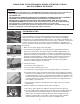
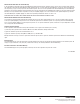
3. Actuator Adjustment
A. Start by loosening the setscrew in the center of
the actuator. Adjust the height of the actuator by
screwing it up or down. There should be a gap (Fig.
4) (about the thickness of a penny) between the
rod and actuator when gently lifting the rod. When
accomplished tighten the setscrew in the center of
the actuator.
3. Réglage de l’actionneur
A. Desserrez d’abord la vis de pression au milieu de
l’actionneur. Réglez la hauteur de l’actionneur en
le faisant pivoter vers le haut ou vers le bas. Il doit
y avoir un espace (fig. 4) (environ de l’épaisseur
d’une pièce d’un cent) entre le levier et l’action-
neur quand on lève doucement le levier. Une fois
le réglage terminé, resserrez la vis de pression au
milieu de l’actionneur.
3. Ajuste del accionador
A. Empiece aflojando el tornillo de fijación del centro
del accionador. Ajuste la altura del accionador ator-
nillando para que suba o baje. Debe haber un huelgo
(Fig. 4) (más o menos el grosor de una moneda
pequeña) entre el vástago y el accionador cuando
se levanta suavemente el vástago. Cuando termine,
apriete el tornillo de fijación del centro del accionador.
4. Check Air Inducer
A. Place several drops of water over hole on top of air
inducer and flush toilet (Fig. 5). If drop is vacuumed
in, move onto step 6. If not, air inducer needs to be
cleaned.
4. Vérification de la soupape d’entrée d’air
A. Versez plusieurs gouttes d’eau dans le trou sur le
dessus de la soupape d’entrée d’air, puis déclen-
chez la chasse (fig. 5). Si les gouttes sont aspirées,
passez à l’étape 6. Sinon, vous devez nettoyer la
soupape d’entrée d’air.
4. Compruebe el inductor de aire
A. Coloque varias gotas de agua sobre el orificio
que está en la parte superior del inductor de aire,
y descargue el excusado (Fig. 5). Si la caída se
absorbe por presión, vaya al Paso 6. Si no, será
necesario limpiar el inductor de aire.
-2-
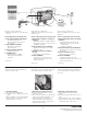
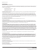
Step 1. Check Flush Cartridge
A. Turn off water supply and flush toilet.
B. Pour water onto top of cartridge (Fig. 1) and turn on water.
C. Watch for air bubbles. Consistent flow of bubbles indicates cartridge needs to be
replaced. No bubbles visible, move on to Step 4.
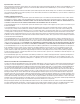
Step 2. Flush Cartridge Replacement
A. Turn off water and flush the toilet.
B. Use the handle end of pliers (Fig. 2) to unscrew the cartridge from the vessel.
C. Drop in new cartridge and screw in until one female thread (Fig. 3) of vessel
is showing.
D. Turn on water. Continue to screw in cartridge slowly, 1/8 to 1/4 turn increments
until water stops running into the bowl and tank pressurizes.
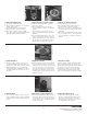
Step 3. Actuator Adjustment
A. Start by loosening the setscrew in the center of the actuator. Adjust the height of
the actuator by screwing it up or down. There should be a gap (Fig. 4) (about the
thickness of a penny) between the rod and actuator when gently lifting the rod.
When accomplished tighten the setscrew in the center of the actuator.
Step 4. Check Air Inducer
A. Place several drops of water over hole on top of air inducer and flush toilet (Fig. 5).
If drop is vacuumed in, move onto step 6. If not, air inducer needs to be cleaned.
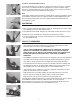
Step 5. Clean Air Inducer
A. Turn off water and flush toilet. Unscrew the cap of the air inducer (the smaller of
the two caps) (Fig. 6).
B. Pull the duckbill out from the cap and clean it by gently squeezing it (Fig. 7)
between your fingers under a flow of water. Inspect the lips of the duckbill.
If they are deformed, the duckbill needs to be replaced.
C. Reassemble, insert the duct bill into the housing (Fig. 8) body and reinstall the cap
to hand tight.
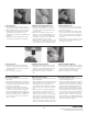
Step 6. Clean Inlet Screen
A. Clean the inlet screen by turning off the water supply, disconnecting the water
supply line from the supply shank and removing the screen with a paper
clip (Fig. 9).
B. Clean screen (Fig. 10) and replace.
Other Points to Remember
1. Pressure-assist toilets get their energy from the water supply.
2. All pressure-assist toilets get their energy from the water supply line. It is important
to have sufficient pressure at the supply. The minimum line pressure for a 1.6 gpf
system is 20 psi and 25 psi for 1.0 gpf.
3. A blocked bowl or drain will affect the fixture’s performance. To check for this, pour
2 to 3 gallons of water into the bowl. If the bowl accumulates water in it, this would
indicate that something is blocking the bowl/drain. If you need additional help,
please contact the manufacturer of the flushing system, or do a word search on
“pressure-assist toilets” on the web.
Fig. 1
Fig. 9
Fig. 4
Fig. 6
Fig. 7
Fig. 8
Fig. 2
Fig. 3
Operation
Fig. 10Fig. 5
All pressure-assist toilets get their energy from the water supply line. It is
important to have sufficient pressure at the supply. The minimum line
pressure for a 1.6 gpf system is 20 psi and 25 psi for 1.0 gpf.
All pressure-assist toilets get their energy from the water supply line. It
is important to have suffi cient pressure at the supply. The minimum line
pressure is 25 psi for 1.0 gpf.
Step 1. Check Flush Cartridge
A. Turn off water supply and fl ush toilet.
B. Pour water onto top of cartridge (Fig. 1) and turn on water.
C. Watch for air bubbles. Consistent fl ow of bubbles indicates cartridge needs to be
replaced. No bubbles visible, move on to Step 4.
Step 2. Flush Cartridge Replacement
A. Turn off water and fl ush the toilet.
B. Use the handle end of pliers (Fig. 2) to unscrew the cartridge from the vessel.
C. Drop in new cartridge and screw in until one female thread (Fig. 3) of vessel
is showing.
D. Turn on water. Continue to screw in cartridge slowly, 1/8 to 1/4 turn increments
until water stops running into the bowl and tank pressurizes.
Step 3. Actuator Adjustment
A. Start by loosening the setscrew in the center of the actuator. Adjust the height of
the actuator by screwing it up or down. There should be a gap (Fig. 4) (about the
thickness of a penn
y) between the rod and actuator when gently lifting the rod.
When accomplished tighten the setscrew in the center of the actuator.
Step 4. Check Air Inducer
A. Place several drops of water over hole on top of air inducer and fl ush toilet (Fig. 5).
If drop is vacuumed in, move onto step 6. If not, air inducer needs to be cleaned.
Step 5. Clean Air Inducer
A. Turn off water and fl ush toilet. Unscrew the cap of the air inducer (the smaller of
the two caps) (Fig. 6).
B. Pull the duckbill out from the cap and clean it by gently squeezing it (Fig. 7)
between your fi ngers under a fl o w o f water. Inspect the lips of the duckbill.
If they are deformed, the duckbill needs to be replaced.
C. Reassemble, insert the duct bill into the housing (Fig. 8) body and reinstall the ca
p
to hand tight.
Step 6. Clean Inlet Screen
A. Clean the inlet screen by turning off the water supply, disconnecting the water
supply line from the supply shank and removing the screen with a paper
clip (Fig. 9).
B. Clean screen (Fig. 10) and replace.
Other Points to Remember
1. Pressure-assist toilets get their energy from the water supply.
2. All pressure-assist toilets get their energy from the water supply line. It is important
to have suffi cient pressure at the supply. The minimum line pressure is 25 psi
for a 1.0 gpf system.
3. A blocked bowl or drain will affect the fi xture’s performance. To check for this, pour
2 to 3 gallons of water into the bowl. If the bowl accumulates water in it, this would
indicate that something is blocking the bowl/drain. If you need additional help,
please contact the manufac
turer of the fl ushing system, or do a word search on
“pressure-assist toilets” on the web.
-2-
Step 1. Check Flush Cartridge
A. Turn off water supply and flush toilet.
B. Pour water onto top of cartridge (Fig. 1) and turn on water.
C. Watch for air bubbles. Consistent flow of bubbles indicates cartridge needs to be
replaced. No bubbles visible, move on to Step 4.
Step 2. Flush Cartridge Replacement
A. Turn off water and flush the toilet.
B. Use the handle end of pliers (Fig. 2) to unscrew the cartridge from the vessel.
C. Drop in new cartridge and screw in until one female thread (Fig. 3) of vessel
is showing.
D. Turn on water. Continue to screw in cartridge slowly, 1/8 to 1/4 turn increments
until water stops running into the bowl and tank pressurizes.
Step 3. Actuator Adjustment
A. Start by loosening the setscrew in the center of the actuator. Adjust the height of
the actuator by screwing it up or down. There should be a gap (Fig. 4) (about the
thickness of a penny) between the rod and actuator when gently lifting the rod.
When accomplished tighten the setscrew in the center of the actuator.
Step 4. Check Air Inducer
A. Place several drops of water over hole on top of air inducer and flush toilet (Fig. 5).
If drop is vacuumed in, move onto step 6. If not, air inducer needs to be cleaned.
Step 5. Clean Air Inducer
A. Turn off water and flush toilet. Unscrew the cap of the air inducer (the smaller of
the two caps) (Fig. 6).
B. Pull the duckbill out from the cap and clean it by gently squeezing it (Fig. 7)
between your fingers under a flow of water. Inspect the lips of the duckbill.
If they are deformed, the duckbill needs to be replaced.
C. Reassemble, insert the duct bill into the housing (Fig. 8) body and reinstall the cap
to hand tight.
Step 6. Clean Inlet Screen
A. Clean the inlet screen by turning off the water supply, disconnecting the water
supply line from the supply shank and removing the screen with a paper
clip (Fig. 9).
B. Clean screen (Fig. 10) and replace.
Other Points to Remember
1. Pressure-assist toilets get their energy from the water supply.
2. All pressure-assist toilets get their energy from the water supply line. It is important
to have sufficient pressure at the supply. The minimum line pressure for a 1.6 gpf
system is 20 psi and 25 psi for 1.0 gpf.
3. A blocked bowl or drain will affect the fixture’s performance. To check for this, pour
2 to 3 gallons of water into the bowl. If the bowl accumulates water in it, this would
indicate that something is blocking the bowl/drain. If you need additional help,
please contact the manufacturer of the flushing system, or do a word search on
“pressure-assist toilets” on the web.
Fig. 1
Fig. 9Fig. 4
Fig. 6
Fig. 7
Fig. 8
Fig. 2
Fig. 3
Operation
Fig. 10
Fig. 5
All pressure-assist toilets get their energy from the water supply line. It is
important to have sufficient pressure at the supply. The minimum line
pressure for a 1.6 gpf system is 20 psi and 25 psi for 1.0 gpf.
All pressure-assist toilets get their energy from the water supply line. It
is important to have suffi cient pressure at the supply. The minimum line
pressure is 25 psi for 1.0 gpf.
Step 1. Check Flush Cartridge
A. Turn off water supply and fl ush toilet.
B. Pour water onto top of cartridge (Fig. 1) and turn on water.
C. Watch for air bubbles. Consistent fl ow of bubbles indicates cartridge needs to be
replaced. No bubbles visible, move on to Step 4.
Step 2. Flush Cartridge Replacement
A. Turn off water and fl ush the toilet.
B. Use the handle end of pliers (Fig. 2) to unscrew the cartridge from the vessel.
C. Drop in new cartridge and screw in until one female thread (Fig. 3) of vessel
is showing.
D. Turn on water. Continue to screw in cartridge slowly, 1/8 to 1/4 turn increments
until water stops running into the bowl and tank pressurizes.
Step 3. Actuator Adjustment
A. Start by loosening the setscrew in the center of the actuator. Adjust the height of
the actuator by screwing it up or down. There should be a gap (Fig. 4) (about the
thickness of a penn
y) between the rod and actuator when gently lifting the rod.
When accomplished tighten the setscrew in the center of the actuator.
Step 4. Check Air Inducer
A. Place several drops of water over hole on top of air inducer and fl ush toilet (Fig. 5).
If drop is vacuumed in, move onto step 6. If not, air inducer needs to be cleaned.
Step 5. Clean Air Inducer
A. Turn off water and fl ush toilet. Unscrew the cap of the air inducer (the smaller of
the two caps) (Fig. 6).
B. Pull the duckbill out from the cap and clean it by gently squeezing it (Fig. 7)
between your fi ngers under a fl o w o f water. Inspect the lips of the duckbill.
If they are deformed, the duckbill needs to be replaced.
C. Reassemble, insert the duct bill into the housing (Fig. 8) body and reinstall the ca
p
to hand tight.
Step 6. Clean Inlet Screen
A. Clean the inlet screen by turning off the water supply, disconnecting the water
supply line from the supply shank and removing the screen with a paper
clip (Fig. 9).
B. Clean screen (Fig. 10) and replace.
Other Points to Remember
1. Pressure-assist toilets get their energy from the water supply.
2. All pressure-assist toilets get their energy from the water supply line. It is important
to have suffi cient pressure at the supply. The minimum line pressure is 25 psi
for a 1.0 gpf system.
3. A blocked bowl or drain will affect the fi xture’s performance. To check for this, pour
2 to 3 gallons of water into the bowl. If the bowl accumulates water in it, this would
indicate that something is blocking the bowl/drain. If you need additional help,
please contact the manufac
turer of the fl ushing system, or do a word search on
“pressure-assist toilets” on the web.
2. Flush Cartridge Replacement
A. Turn off water and flush the toilet.
B. Use the handle end of pliers (Fig. 2) to unscrew the
cartridge from the vessel.
C. Drop in new cartridge and screw in until one
female thread (Fig. 3) of vessel is showing.
D. Turn on water. Continue to screw in cartridge
slowly, 1/8 to 1/4 turn increments until water stops
running into the bowl and tank pressurizes.
2. Remplacement de la cartouche de chasse
A. Fermez le robinet d’alimentation en eau, puis
déclenchez la chasse.
B. Utilisez l’extrémité des manches d’une pince
(fig. 2) pour dévisser la cartouche et la retirer du
récipient.
C. Insérez la nouvelle cartouche, puis vissez-la
jusqu’à ce qu’un filet femelle (fig. 3) du récipient
apparaisse.
D. Ouvrez le robinet d’alimentation en eau. Contin-
uez à visser lentement la artouche en faisant un
huitième ou un quart de tour à la fois, jusqu’à ce
que l’eau arrête de s’écouler dans la cuvette et
que la pression soit rétablie dans le réservoir.
2. Repuesto del cartucho de descarga
A. Cierre el agua y descargue el excusado.
B. Use el extremo del mango de las pinzas (Fig. 2)
para desatornillar el cartucho de la vasija.
C. Deje caer un nuevo cartucho y atorníllelo hasta que
se esté viendo una vuelta de rosca hembra (Fig. 3)
de la vasija.
D. Abra el agua. Siga atornillando el cartucho lentam-
ente, en incrementos de 1/8 a 1/4 de vuelta hasta
que el agua deje de correr al lavabo y el tanque se
presurice.
-2-
Step 1. Check Flush Cartridge
A. Turn off water supply and flush toilet.
B. Pour water onto top of cartridge (Fig. 1) and turn on water.
C. Watch for air bubbles. Consistent flow of bubbles indicates cartridge needs to be
replaced. No bubbles visible, move on to Step 4.
Step 2. Flush Cartridge Replacement
A. Turn off water and flush the toilet.
B. Use the handle end of pliers (Fig. 2) to unscrew the cartridge from the vessel.
C. Drop in new cartridge and screw in until one female thread (Fig. 3) of vessel
is showing.
D. Turn on water. Continue to screw in cartridge slowly, 1/8 to 1/4 turn increments
until water stops running into the bowl and tank pressurizes.
Step 3. Actuator Adjustment
A. Start by loosening the setscrew in the center of the actuator. Adjust the height of
the actuator by screwing it up or down. There should be a gap (Fig. 4) (about the
thickness of a penny) between the rod and actuator when gently lifting the rod.
When accomplished tighten the setscrew in the center of the actuator.
Step 4. Check Air Inducer
A. Place several drops of water over hole on top of air inducer and flush toilet (Fig. 5).
If drop is vacuumed in, move onto step 6. If not, air inducer needs to be cleaned.
Step 5. Clean Air Inducer
A. Turn off water and flush toilet. Unscrew the cap of the air inducer (the smaller of
the two caps) (Fig. 6).
B. Pull the duckbill out from the cap and clean it by gently squeezing it (Fig. 7)
between your fingers under a flow of water. Inspect the lips of the duckbill.
If they are deformed, the duckbill needs to be replaced.
C. Reassemble, insert the duct bill into the housing (Fig. 8) body and reinstall the cap
to hand tight.
Step 6. Clean Inlet Screen
A. Clean the inlet screen by turning off the water supply, disconnecting the water
supply line from the supply shank and removing the screen with a paper
clip (Fig. 9).
B. Clean screen (Fig. 10) and replace.
Other Points to Remember
1. Pressure-assist toilets get their energy from the water supply.
2. All pressure-assist toilets get their energy from the water supply line. It is important
to have sufficient pressure at the supply. The minimum line pressure for a 1.6 gpf
system is 20 psi and 25 psi for 1.0 gpf.
3. A blocked bowl or drain will affect the fixture’s performance. To check for this, pour
2 to 3 gallons of water into the bowl. If the bowl accumulates water in it, this would
indicate that something is blocking the bowl/drain. If you need additional help,
please contact the manufacturer of the flushing system, or do a word search on
“pressure-assist toilets” on the web.
Fig. 1
Fig. 9Fig. 4
Fig. 6
Fig. 7
Fig. 8
Fig. 2
Fig. 3
Operation
Fig. 10Fig. 5
All pressure-assist toilets get their energy from the water supply line. It is
important to have sufficient pressure at the supply. The minimum line
pressure for a 1.6 gpf system is 20 psi and 25 psi for 1.0 gpf.
All pressure-assist toilets get their energy from the water supply line. It
is important to have suffi cient pressure at the supply. The minimum line
pressure is 25 psi for 1.0 gpf.
Step 1. Check Flush Cartridge
A. Turn off water supply and fl ush toilet.
B. Pour water onto top of cartridge (Fig. 1) and turn on water.
C. Watch for air bubbles. Consistent fl ow of bubbles indicates cartridge needs to be
replaced. No bubbles visible, move on to Step 4.
Step 2. Flush Cartridge Replacement
A. Turn off water and fl ush the toilet.
B. Use the handle end of pliers (Fig. 2) to unscrew the cartridge from the vessel.
C. Drop in new cartridge and screw in until one female thread (Fig. 3) of vessel
is showing.
D. Turn on water. Continue to screw in cartridge slowly, 1/8 to 1/4 turn increments
until water stops running into the bowl and tank pressurizes.
Step 3. Actuator Adjustment
A. Start by loosening the setscrew in the center of the actuator. Adjust the height of
the actuator by screwing it up or down. There should be a gap (Fig. 4) (about the
thickness of a penn
y) between the rod and actuator when gently lifting the rod.
When accomplished tighten the setscrew in the center of the actuator.
Step 4. Check Air Inducer
A. Place several drops of water over hole on top of air inducer and fl ush toilet (Fig. 5).
If drop is vacuumed in, move onto step 6. If not, air inducer needs to be cleaned.
Step 5. Clean Air Inducer
A. Turn off water and fl ush toilet. Unscrew the cap of the air inducer (the smaller of
the two caps) (Fig. 6).
B. Pull the duckbill out from the cap and clean it by gently squeezing it (Fig. 7)
between your fi ngers under a fl o w o f water. Inspect the lips of the duckbill.
If they are deformed, the duckbill needs to be replaced.
C. Reassemble, insert the duct bill into the housing (Fig. 8) body and reinstall the ca
p
to hand tight.
Step 6. Clean Inlet Screen
A. Clean the inlet screen by turning off the water supply, disconnecting the water
supply line from the supply shank and removing the screen with a paper
clip (Fig. 9).
B. Clean screen (Fig. 10) and replace.
Other Points to Remember
1. Pressure-assist toilets get their energy from the water supply.
2. All pressure-assist toilets get their energy from the water supply line. It is important
to have suffi cient pressure at the supply. The minimum line pressure is 25 psi
for a 1.0 gpf system.
3. A blocked bowl or drain will affect the fi xture’s performance. To check for this, pour
2 to 3 gallons of water into the bowl. If the bowl accumulates water in it, this would
indicate that something is blocking the bowl/drain. If you need additional help,
please contact the manufacturer of the fl ushing system, or do a word search on
“pressure-assist toilets” on the web.
-2-
Step 1. Check Flush Cartridge
A. Turn off water supply and flush toilet.
B. Pour water onto top of cartridge (Fig. 1) and turn on water.
C. Watch for air bubbles. Consistent flow of bubbles indicates cartridge needs to be
replaced. No bubbles visible, move on to Step 4.
Step 2. Flush Cartridge Replacement
A. Turn off water and flush the toilet.
B. Use the handle end of pliers (Fig. 2) to unscrew the cartridge from the vessel.
C. Drop in new cartridge and screw in until one female thread (Fig. 3) of vessel
is showing.
D. Turn on water. Continue to screw in cartridge slowly, 1/8 to 1/4 turn increments
until water stops running into the bowl and tank pressurizes.
Step 3. Actuator Adjustment
A. Start by loosening the setscrew in the center of the actuator. Adjust the height of
the actuator by screwing it up or down. There should be a gap (Fig. 4) (about the
thickness of a penny) between the rod and actuator when gently lifting the rod.
When accomplished tighten the setscrew in the center of the actuator.
Step 4. Check Air Inducer
A. Place several drops of water over hole on top of air inducer and flush toilet (Fig. 5).
If drop is vacuumed in, move onto step 6. If not, air inducer needs to be cleaned.
Step 5. Clean Air Inducer
A. Turn off water and flush toilet. Unscrew the cap of the air inducer (the smaller of
the two caps) (Fig. 6).
B. Pull the duckbill out from the cap and clean it by gently squeezing it (Fig. 7)
between your fingers under a flow of water. Inspect the lips of the duckbill.
If they are deformed, the duckbill needs to be replaced.
C. Reassemble, insert the duct bill into the housing (Fig. 8) body and reinstall the cap
to hand tight.
Step 6. Clean Inlet Screen
A. Clean the inlet screen by turning off the water supply, disconnecting the water
supply line from the supply shank and removing the screen with a paper
clip (Fig. 9).
B. Clean screen (Fig. 10) and replace.
Other Points to Remember
1. Pressure-assist toilets get their energy from the water supply.
2. All pressure-assist toilets get their energy from the water supply line. It is important
to have sufficient pressure at the supply. The minimum line pressure for a 1.6 gpf
system is 20 psi and 25 psi for 1.0 gpf.
3. A blocked bowl or drain will affect the fixture’s performance. To check for this, pour
2 to 3 gallons of water into the bowl. If the bowl accumulates water in it, this would
indicate that something is blocking the bowl/drain. If you need additional help,
please contact the manufacturer of the flushing system, or do a word search on
“pressure-assist toilets” on the web.
Fig. 1
Fig. 9Fig. 4
Fig. 6
Fig. 7
Fig. 8
Fig. 2
Fig. 3
Operation
Fig. 10Fig. 5
All pressure-assist toilets get their energy from the water supply line. It is
important to have sufficient pressure at the supply. The minimum line
pressure for a 1.6 gpf system is 20 psi and 25 psi for 1.0 gpf.
All pressure-assist toilets get their energy from the water supply line. It
is important to have suffi cient pressure at the supply. The minimum line
pressure is 25 psi for 1.0 gpf.
Step 1. Check Flush Cartridge
A. Turn off water supply and fl ush toilet.
B. Pour water onto top of cartridge (Fig. 1) and turn on water.
C. Watch for air bubbles. Consistent fl ow of bubbles indicates cartridge needs to be
replaced. No bubbles visible, move on to Step 4.
Step 2. Flush Cartridge Replacement
A. Turn off water and fl ush the toilet.
B. Use the handle end of pliers (Fig. 2) to unscrew the cartridge from the vessel.
C. Drop in new cartridge and screw in until one female thread (Fig. 3) of vessel
is showing.
D. Turn on water. Continue to screw in cartridge slowly, 1/8 to 1/4 turn increments
until water stops running into the bowl and tank pressurizes.
Step 3. Actuator Adjustment
A. Start by loosening the setscrew in the center of the actuator. Adjust the height of
the actuator by screwing it up or down. There should be a gap (Fig. 4) (about the
thickness of a penn
y) between the rod and actuator when gently lifting the rod.
When accomplished tighten the setscrew in the center of the actuator.
Step 4. Check Air Inducer
A. Place several drops of water over hole on top of air inducer and fl ush toilet (Fig. 5).
If drop is vacuumed in, move onto step 6. If not, air inducer needs to be cleaned.
Step 5. Clean Air Inducer
A. Turn off water and fl ush toilet. Unscrew the cap of the air inducer (the smaller of
the two caps) (Fig. 6).
B. Pull the duckbill out from the cap and clean it by gently squeezing it (Fig. 7)
between your fi ngers under a fl o w o f water. Inspect the lips of the duckbill.
If they are deformed, the duckbill needs to be replaced.
C. Reassemble, insert the duct bill into the housing (Fig. 8) body and reinstall the ca
p
to hand tight.
Step 6. Clean Inlet Screen
A. Clean the inlet screen by turning off the water supply, disconnecting the water
supply line from the supply shank and removing the screen with a paper
clip (Fig. 9).
B. Clean screen (Fig. 10) and replace.
Other Points to Remember
1. Pressure-assist toilets get their energy from the water supply.
2. All pressure-assist toilets get their energy from the water supply line. It is important
to have suffi cient pressure at the supply. The minimum line pressure is 25 psi
for a 1.0 gpf system.
3. A blocked bowl or drain will affect the fi xture’s performance. To check for this, pour
2 to 3 gallons of water into the bowl. If the bowl accumulates water in it, this would
indicate that something is blocking the bowl/drain. If you need additional help,
please contact the manufac
turer of the fl ushing system, or do a word search on
“pressure-assist toilets” on the web.