
Installation Sheet
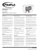
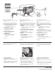
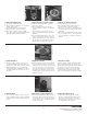
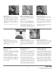
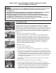

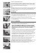
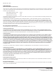
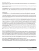

Figure 6
Figure 7a
Figure 7b
Figure 7c
Figure 7d
Figure 8
Figure 9
6
c. Examine the exposed O-rings on the Flush Valve Cartridge for obstruction or
damage. If the O-rings are damaged, the Flush Valve Cartridge should be
replaced. Clean any debris from the O-ring before re-installing.
(See Figure 4)
d. Insert the Flush Valve Cartridge into the
FLUSHMATE
®
tank and thread it
clockwise into place until one (1) black thread (on the
FLUSHMATE
®
tank) is
showing above the Flush Valve Cartridge.
(See Figure 5)
Fully open the water
supply valve and continue to thread the Flush Valve Cartridge clockwise, 1/4
turn at a time, pausing briefly between each 1/4 turn, until the water stops
running into the toilet bowl and the
FLUSHMATE
®
tank pressurizes.
e. Test setup by flushing toilet. Reinstall Flush Rod and handle linkage.
B) Condition:
Weak, incomplete, sluggish, or no flush
Inadequate water pressure, an improperly adjusted Flush Valve Cartridge, a clogged
inlet screen, or insufficient air draw may cause a weak, sluggish, or no flush condition.
1. Make sure that the water supply valve is fully open.
2. Check for proper actuation adjustment, see Condition A-2, “Water runs and will not
shut off.”
3. Turn off the water supply valve.
4. Flush the toilet to relieve the pressure.
5. Disconnect the water supply line from the Supply Shank (A).
(See Figure 6)
a. Examine the inlet screen and remove anything that may be blocking the flow of
water into the
FLUSHMATE
®
tank. The inlet screen can be removed by inserting
a pointed object (such as a large paperclip or the blade of a penknife) into the
lower Supply Shank and working the inlet screen loose.
(See Figures 7a, 7b, 7c)
The inlet screen easily snaps back into position by pushing it upward into the
Supply Shank with your fingertip.
(See Figure 7d)
6. Examine the Air Inducer (D) for obstruction or damage.
(See Figure 8)
a. Make sure the water supply valve is turned off and the toilet has been flushed to
relieve the pressure.
b. Remove the Air Inducer Cap.
(See Figure 9)
c. Remove the Duckbill Valve from the Air Inducer Cap.
(See Figure 10)
The flat
“lips” of Duckbill Valve should open fully when the square sides are squeezed
together.
(See Figure 11)
Rinse any obstruction or mineral deposits from the
Duckbill Valve. If the Duckbill Valve is damaged, it must be replaced.
d. Insert the Duckbill Valve into the Air Inducer housing.
(See Figure 12)
e. Put the Air Inducer Cap back on, and tighten finger-tight only.
(See Figure 13)
f. Reconnect the water supply line and fully open water supply valve.
7. Check Air Inducer for sufficient air draw. Place a small amount of water (two to
three drops) over the hole on top of the Air Inducer Cap
(See Figure 14)
and flush
the toilet. If the Air Inducer is working properly, the water will be drawn in.
(See
Figure 15)
8. Check the Flush Valve Cartridge for leaks. Pour a small amount of water into the
Cartridge housing area.
(See Figure 16)
If bubbles are coming from the center or
the edge of the Flush Valve Cartridge, it should be replaced.