Model No. 831.23953.1 Serial No. Write the serial number in the space above for reference. Serial Number Decal (under frame) • Assembly • Operation • Maintenance • Part List and Drawing Sears, Roebuck and Co. Hoffman Estates, IL 60179 CAUTION Read all precautions and instructions in this manual before using this equipment. Keep this manual for future reference.
TABLE OF CONTENTS WARNING DECAL PLACEMENT . . . . . . . . . . . . . . . . . . . . . . . . . . . . . . . . . . . . . . . . . . . . . . . . . . . . . . . . . . . . . . . 2 IMPORTANT PRECAUTIONS . . . . . . . . . . . . . . . . . . . . . . . . . . . . . . . . . . . . . . . . . . . . . . . . . . . . . . . . . . . . . . . . . . 3 BEFORE YOU BEGIN. . . . . . . . . . . . . . . . . . . . . . . . . . . . . . . . . . . . . . . . . . . . . . . . . . . . . . . . . . . . . . . . . . . . . . . .
IMPORTANT PRECAUTIONS WARNING: To reduce the risk of serious injury, read all important precautions and instructions in this manual and all warnings on your elliptical before using your elliptical. Sears assumes no responsibility for personal injury or property damage sustained by or through the use of this product. 1. Before beginning any exercise program, consult your physician. This is especially important for persons over age 35 or persons with pre-existing health problems. 9.
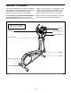
BEFORE YOU BEGIN Thank you for selecting the revolutionary PROFORM® 395 E elliptical. The 395 E elliptical provides an impressive selection of features designed to make your workouts at home more effective and enjoyable. manual. To help us assist you, note the product model number and serial number before contacting us. The model number and the location of the serial number decal are shown on the front cover of this manual. For your benefit, read this manual carefully before you use the elliptical.
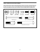
PART IDENTIFICATION CHART Use the drawings below to identify the small parts needed for assembly. The number in parentheses below each drawing is the key number of the part, from the PART LIST near the end of this manual. The number following the key number is the quantity needed for assembly. Note: If a part is not in the hardware kit, check to see if it has been preassembled. Extra parts may be included. If a part is missing, please call 1-888-533-1333.
ASSEMBLY • Assembly requires two persons. • In addition to the included tool(s), assembly requires the following tools: • Place all parts in a cleared area and remove the packing materials. Do not dispose of the packing materials until you complete all assembly steps. one Phillips screwdriver • To identify small parts, see page 5. Assembly may be easier if you have your own set of wrenches. To avoid damaging parts, do not use power tools. 1.
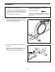
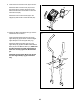
3. Orient the Upright (2) and the Shield Cover (37) as shown. Slide the Shield Cover upward onto the Upright. 3 Wire Tie Have a second person hold the Upright (2) and the Shield Cover (37) near the Frame (1). 2 Locate the wire tie in the lower end of the Upright (2). Tie the wire tie to the Main Wire (42). Then, pull the upper end of the wire tie until the Main Wire is routed through the Upright.
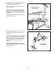
4. Tip: Avoid pinching the Main Wire (42). Slide the Upright (2) onto the Frame (1). 4 Have a second person hold the Shield Cover (37) out of the way. Avoid pinching the Main Wire (42) Attach the Upright (2) with five M10 x 20mm Screws (79) and five M10 Split Washers (78). Tip: Start all the Screws before fully tightening them. 37 Press the Shield Cover (37) into the Left and Right Shields (44, 45). 2 44, 45 79 78 78 79 1 5. Orient the Handlebar (39) as shown.
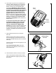
6. The Console (4) can use four D batteries (not included); alkaline batteries are recommended. Do not use old and new batteries together or alkaline, standard, and rechargeable batteries together. IMPORTANT: If the Console has been exposed to cold temperatures, allow it to warm to room temperature before inserting batteries. Otherwise, you may damage the console displays or other electronic components.
9. Orient the Front Console Cover (32) as shown. 9 32 Attach the Rear Console Cover (81) around the Upright (2) by pressing the hooks on the Rear Console Cover into the tabs on the Front Console Cover (32). 92 Attach the Front Console Cover (32) to the Upright (2) with two M4 x 16mm Screws (92). 81 2 10. Identify the Right Upper Body Arm (9), which is marked with an “R” sticker. 10 Orient the Right Upper Body Arm (9) and an Upper Body Leg (6) as shown.
. Using a small plastic bag to keep your fingers clean, apply a generous amount of the included grease to the axle on the right side of the Upright (2). 11 Slide the Right Upper Body Arm (9) onto the Upright (2). Attach the Right Upper Body Arm (9) with an M8 x 20mm Screw (80) and an M8 Washer (33). Repeat this step on the other side of the elliptical. 8 2 Grease 9 33 80 12. Apply a small amount of grease to a Bolt Set (31).
13. Identify a Pivot Cover A (19), which has hooks, and a Pivot Cover B (22), which has tabs. 13 Attach a Pivot Cover A (19) and a Pivot Cover B (22) around the Right Upper Body Arm (9) by pressing the hooks on the Pivot Cover A onto the tabs on the Pivot Cover B. Repeat this step on the other side of the elliptical. 8 Tip: Make sure that the Pivot Covers (19, 22) are positioned as shown. 19 9 22 22 19 14. Orient the Rear Upright Cover (3) as shown.
15. Orient the Front Upright Cover (16) as shown. 15 Attach the Front Upright Cover (16) around the Upright (2) by pressing the hooks on the Front Upright Cover onto the tabs on the Rear Upright Cover (3). 16 2 3 16. Insert the Accessory Tray (5) into the Rear Upright Cover (3). 16 5 3 17. Attach a Front Leg Cover (20) and a Rear Leg Cover (21) around the right Upper Body Leg (6) by pressing the hooks on the Front Leg Cover onto the tabs on the Rear Leg Cover.
18. Identify the Right Pedal (13), which is marked with a “Right” sticker, and orient it as shown. 18 13 Attach the Right Pedal (13) to the Right Pedal Arm (49) with three M10 x 45mm Screws (75) and three M10 Split Washers (78). Make sure to use the center hole and the two outer holes to attach the Right Pedal. 49 Repeat this step on the other side of the elliptical. 78 75 19. Make sure that all parts of the elliptical are properly tightened.
HOW TO USE THE ELLIPTICAL HOW TO MOVE THE ELLIPTICAL HOW TO EXERCISE ON THE ELLIPTICAL Due to the size and weight of the elliptical, moving it requires two persons. Stand in front of the elliptical, hold the upright, and place one foot against one of the front wheels. Pull on the upright and have a second person lift the handle on the rear stabilizer until the elliptical will roll on the wheels. Carefully move the elliptical to the desired location, and then lower it to the floor.
CONSOLE DIAGRAM FEATURES OF THE CONSOLE You can even connect your MP3 player or CD player to the console sound system and listen to your favorite music or audio books while you exercise. The advanced console offers an array of features designed to make your workouts more effective and enjoyable. To use the manual mode, see page 17. To use a preset workout, see page 18. To use the sound system, see page 19.
HOW TO USE THE MANUAL MODE Profile—When a workout is selected, this display mode will show a profile of the resistance settings of the workout. 1. Turn on the console. Press any button or begin pedaling to turn on the console. Pulse—This display mode will show your heart rate when you use the handgrip heart rate monitor (see step 5 on page 18). When you turn on the console, the display will turn on. A tone will sound and the console will be ready for use.
5. Measure your heart rate if desired. HOW TO USE A PRESET WORKOUT If there are sheets of plastic on the metal Contacts contacts on the handgrip heart rate monitor, remove the plastic. In addition, make sure that your hands are clean. To measure your heart rate, hold the handgrip heart rate monitor with your palms resting against the contacts. Avoid moving your hands or gripping the contacts tightly. 1. Turn on the console. Press any button or begin pedaling to turn on the console.
If the resistance level for the current segment is too high or too low, you can manually override the setting by pressing the Resistance buttons. However, when the current segment ends, the pedals will automatically adjust to the resistance level for the next segment. 6. Turn on the fan if desired. If you stop pedaling for several seconds, a series of tones will sound and the workout will pause. See step 7 on page 18. See step 6 on page 18. 7.
MAINTENANCE AND TROUBLESHOOTING Inspect and tighten all parts of the elliptical regularly. Replace any worn parts immediately. Note: For clarity, the pedal disc is shown removed in the drawing below. To clean the elliptical, use a damp cloth and a small amount of mild soap. IMPORTANT: To avoid damage to the console, keep liquids away from the console and keep the console out of direct sunlight. Next, locate the Reed Switch (58). Loosen, but do not remove, the M4 x 16mm Screw (92).
HOW TO ADJUST THE DRIVE BELT Loosen the Pivot Screw (88). Then, tighten the Drive Belt Adjustment Screw (72) until the Drive Belt (46) is tight. If you can feel the pedals slip while you are pedaling, even when the resistance is adjusted to the highest level, the drive belt may need to be adjusted. To adjust the drive belt, you must remove the shield cover and the left shield (see the instructions below). 46 See EXPLODED DRAWING B on page 27.
EXERCISE GUIDELINES Burning Fat—To burn fat effectively, you must exercise at a low intensity level for a sustained period of time. During the first few minutes of exercise, your body uses carbohydrate calories for energy. Only after the first few minutes of exercise does your body begin to use stored fat calories for energy. If your goal is to burn fat, adjust the intensity of your exercise until your heart rate is near the lowest number in your training zone.
SUGGESTED STRETCHES The correct form for several basic stretches is shown at the right. Move slowly as you stretch—never bounce. 1. Toe Touch Stretch Stand with your knees bent slightly and slowly bend forward from your hips. Allow your back and shoulders to relax as you reach down toward your toes as far as possible. Hold for 15 counts, then relax. Repeat 3 times. Stretches: Hamstrings, back of knees and back. 1 2. Hamstring Stretch 2 Sit with one leg extended.
NOTES 24
PART LIST Key No. Qty. 1 2 3 4 5 6 7 8 9 10 11 12 13 14 15 16 17 18 19 20 21 22 23 24 25 26 27 28 29 30 31 32 33 34 35 36 37 38 39 40 41 42 43 44 45 46 47 48 49 50 1 1 1 1 1 2 1 1 1 2 2 1 1 1 2 1 4 10 2 2 2 2 4 1 1 2 1 2 4 2 2 1 4 1 1 1 1 2 1 2 2 1 2 1 1 1 2 2 1 2 Model No. 831.23953.1 R0112A Description Key No. Qty.
30 85 33 29 22 80 33 26 29 14 78 84 12 15 17 8 84 75 17 10 11 21 19 78 23 31 76 6 81 23 95 79 31 92 78 79 3 77 78 20 4 5 78 29 79 79 2 29 92 92 33 85 16 78 30 10 21 19 28 75 13 15 84 39 79 93 31 49 84 17 78 76 79 32 17 23 9 92 23 6 80 31 20 77 33 22 11 EXPLODED DRAWING A Model No. 831.23953.
92 18 97 18 44 59 18 92 27 18 26 92 96 92 26 47 48 24 82 27 92 70 86 41 47 89 38 40 89 41 35 56 92 34 57 90 72 58 92 48 66 88 43 91 77 71 55 83 87 7 42 38 52 36 40 53 65 77 74 54 94 51 64 1 69 63 97 92 50 37 25 45 73 92 46 67 63 62 60 68 92 50 61 43 82 EXPLODED DRAWING B Model No. 831.23953.
90 DAY FULL WARRANTY If this Sears Bike Exerciser fails due to a defect in material or workmanship within 90 days of the date of purchase, call 1-800-4-MY-HOME® (1-800-469-4663) to arrange for free repair (or replacement if repair proves impossible). There is a 5 year warranty on the frame. This warranty does not apply when the Bike Exerciser is used commercially or for rental purposes. This warranty gives you specific legal rights, and you may also have other rights which vary from state to state.