www.proform.com Model No. PFTL70010.0 Serial No. Write the serial number in the space above for reference. Serial Number Decal QUESTIONS? If you have questions, or if parts are damaged or missing, DO NOT CONTACT THE STORE; please contact Customer Care. IMPORTANT: Please register this product (see the limited warranty on the back cover of this manual) before contacting Customer Care. 1-888-533-1333 CALL TOLL-FREE: Mon.–Fri. 6 a.m.–6 p.m. MT Sat. 8 a.m.–4 p.m. MT ON THE WEB: www.proformservice.
TABLE OF CONTENTS WARNING DECAL PLACEMENT . . . . . . . . . . . . . . . . . . . . . . . . . . . . . . . . . . . . . . . . . . . . . . . . . . . . . . . . . . . . . .2 IMPORTANT PRECAUTIONS . . . . . . . . . . . . . . . . . . . . . . . . . . . . . . . . . . . . . . . . . . . . . . . . . . . . . . . . . . . . . . . .3 BEFORE YOU BEGIN . . . . . . . . . . . . . . . . . . . . . . . . . . . . . . . . . . . . . . . . . . . . . . . . . . . . . . . . . . . . . . . . . . . . . .5 ASSEMBLY . . . . . . . . . . . . .
IMPORTANT PRECAUTIONS WARNING: To reduce the risk of serious injury, read all important precautions and instructions in this manual and all warnings on your treadmill before using your treadmill. ICON assumes no responsibility for personal injury or property damage sustained by or through the use of this product. 1. Before beginning any exercise program, consult your physician. This is especially important for persons over age 35 or persons with pre-existing health problems. carrying 15 or more amps.
24. Inspect and properly tighten all parts of the treadmill regularly. 20. Never leave the treadmill unattended while it is running. Always remove the key, unplug the power cord, and press the power switch into the off position when the treadmill is not in use. (See the drawing on page 5 for the location of the power switch.) 25. 21. Do not attempt to raise, lower, or move the treadmill until it is properly assembled. (See ASSEMBLY on page 6, and HOW TO FOLD AND MOVE THE TREADMILL on page 24.
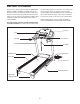
BEFORE YOU BEGIN Thank you for selecting the revolutionary PROFORM® 600 LT treadmill. The 600 LT treadmill offers an impressive selection of features designed to make your workouts at home more enjoyable and effective. And when youʼre not exercising, the unique treadmill can be folded up, requiring less than half the floor space of other treadmills. ing this manual, please see the front cover of this manual.
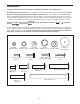
ASSEMBLY To hire an authorized service technician to assemble the treadmill, call 1-800-445-2480. Assembly requires two persons. Set the treadmill in a cleared area and remove all packing materials. Do not dispose of the packing materials until assembly is completed. Note: The underside of the treadmill walking belt is coated with high-performance lubricant. During shipping, some lubricant may be transferred to the top of the walking belt or the shipping carton.
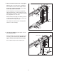
1. Make sure that the power cord is unplugged. 1 With the help of a second person, carefully tip the treadmill onto its left side. Partially fold the Frame (53) so that the treadmill is more stable; do not fully fold the Frame yet. Hole 88 89 6 Cut the shipping tie securing the Upright Wire (88) to the Base (91). Locate a plastic tie in the indicated hole in the Base, and use the tie to pull the Upright Wire out of the hole.
3. Identify the Right Upright (81), which is marked with a “Right” sticker. Hold the Right Upright near the Base (91) as shown. 3 81 See the inset drawing. Tie the wire tie in the Right Upright (81) securely around the end of the Upright Wire (88). Then, pull the other end of the wire tie until the Upright Wire is routed completely through the Right Upright. 88 88 Wire Tie 91 81 88 4. Hold the Right Upright (81) against the Base (91). Be careful not to pinch the Upright Wire (88).
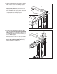
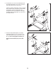
5. With the help of a second person, carefully tip the treadmill onto its right side. Partially fold the Frame (53) so that the treadmill is more stable; do not fully fold the Frame yet. 5 110 Attach a Wheel (93) to the Base (91) with a 3/8" x 2" Bolt (9) and a 3/8" Nut (10). Do not overtighten the Nut; the Wheel must turn freely. 9 Press a Base Cap (110) into the Base (91). 91 6. Hold the Left Upright (80) against the Base (91).
8. Cut the plastic tie in the Left Handrail (84) and the Right Handrail (85). If necessary, press the 5/16" Cage Nuts (31) back into place. 8 31 84 Identify the Right Handrail (85), which is marked with a “Right” sticker, and hold it near the Right Upright (81). Insert the Upright Wire (88) through the bracket on the bottom of the Right Handrail. Pull the Upright Wire out of the end of the Right Handrail. Tie 88 Tie 31 85 81 9.
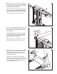
10. Set the console assembly face down on a soft surface to avoid scratching the console assembly. Remove the two Screws (A). Next, lift off the Crossbar (107). Discard the two Screws. 10 Console Assembly A 107 11. IMPORTANT: To avoid damaging the Crossbar (107), do not use power tools and do not overtighten the #10 x 3/4" Screws (4) or the #10 x 3/4" Flat Head Screws (109). 11 109 84 Orient the Crossbar (107) as shown.
. With the help of a second person, hold the console assembly near the Right Handrail (85). Connect the Upright Wire (88) to the console wire. See the inset drawing. The connectors should slide together easily and snap into place. If they do not, turn one connector and try again. IF YOU DO NOT CONNECT THE CONNECTORS PROPERLY, THE CONSOLE MAY BECOME DAMAGED WHEN YOU TURN ON THE POWER. Remove the wire tie from the Upright Wire. 12 Console Assembly Console Wire 88 Wire Tie 85 13.
14. Firmly tighten the four the 3/8" x 4" Bolts (7) and the two 3/8" x 1 1/2" Bolts (8) (only one side is shown). 14 Side the Left Base Cover (86) and the Right Base Cover (87) down towards the floor. 86 87 7 15. Slide the Left Handrail Cover (83) onto the Left Handrail (84). Slide the Right Handrail Cover (55) onto the Right Handrail (85). Attach the Handrail Covers with two #8 x 1/2" Screws (16).
16. Hold the Left Upright Cover (78) against the console assembly. Align the holes in the Left Upright Cover with the holes in the Left Upright (80). Attach the Left Upright Cover with three #8 x 1/2" Screws (16). 16 Attach the Right Upright Cover (79) to the Right Upright (81) in the same way. 79 81 17. Attach the Left Tray (101) and the Right Tray (102) to the console assembly with four #8 x 1/2" Screws (16).
18. Raise the Frame (53) to the position shown. Have a second person hold the Frame until this step is completed. 18 Orient the Storage Latch (52) so that the large barrel and the latch knob are oriented as shown. 53 10 Attach the Latch Bracket (51) and Storage Latch (52) to the Base (91) with two 3/8" x 2" Bolts (9) and two 3/8" Nuts (10). 9 52 Latch Knob Attach the upper end of the Storage Latch (52) to the bracket on the Frame (53) with a 3/8" x 2" Bolt (9) and a 3/8" Nut (10).
OPERATION AND ADJUSTMENT THE PRE-LUBRICATED WALKING BELT dance with all local codes and ordinances. IMPORTANT: The treadmill is not compatible with GFCI-equipped outlets and may not be compatible with AFCI-equipped outlets. Your treadmill features a walking belt coated with highperformance lubricant. IMPORTANT: Never apply silicone spray or other substances to the walking belt or the walking platform. Such substances will cause excessive wear.
CONSOLE DIAGRAM FEATURES OF THE CONSOLE You can even listen to your favorite workout music or audio books with the consoleʼs stereo sound system while you exercise. The treadmill console offers an impressive array of features designed to make your workouts more effective and enjoyable. When you use the manual mode, you can change the speed and incline of the treadmill with the touch of a button. As you exercise, the console will display instant exercise feedback.
HOW TO TURN ON THE POWER IMPORTANT: If the treadmill has been exposed to cold temperatures, allow it to warm to room temperature before turning on the power. If you do not do this, you may damage the console displays or other electrical components. Plug in the power cord (see page 16). Next, locate the power switch on the treadmill frame near the power cord. Press the power switch into the reset position. Reset HOW TO USE THE MANUAL MODE 1. Insert the key into the console.
5. Follow your progress with the displays. To measure your heart rate, stand on the foot rails and hold the pulse bar with your palms on the metal conContacts tacts; avoid moving your hands. When your pulse is detected, several dashes will appear and then your heart rate will be shown. For the most accurate heart rate reading, continue to hold the contacts for about 15 seconds. The matrix—When you select the manual mode, the matrix will display a track that represents 1/4 mile (400 meters).
HOW TO USE AN ONBOARD WORKOUT grammed for the next segment, the new speed and/or incline setting will flash in the displays for a few seconds. The treadmill will automatically adjust to the new speed and/or incline setting. 1. Insert the key into the console. See HOW TO TURN ON THE POWER on page 18. The workout will continue in this way until the last segment of the profile flashes in the display and the last segment ends. The walking belt will then slow to a stop. 2. Select an onboard workout.
4. Follow your progress with the displays. HOW TO USE THE WEIGHT LOSS CENTER 1. Insert the key into the console. See step 5 on page 19. Note: The calorie goal is an estimate of the number of calories that you will burn during the workout. The actual number of calories that you burn will depend on your weight. In addition, if you manually change the speed or incline of the treadmill during the workout, the number of calories you burn will be affected. See HOW TO TURN ON THE POWER on page 18. 2.
HOW TO USE AN IFIT WORKOUT the button, the treadmill will automatically adjust to the first speed and incline settings of the workout. Hold the handrails and begin walking. To purchase iFit cards at any time, go to www.iFit.com or call the telephone number on the front cover of this manual. iFit cards are also available at select stores. During the workout, the voice of a personal trainer will guide you through the workout. 1. Insert the key into the console.
THE INFORMATION MODE The console features an information mode that keeps track of the total distance that the walking belt has moved and the total number of hours that the treadmill has been used. The information mode also allows you to select miles or kilometers to measure distance, and to turn on and turn off the display demo mode. To select the information mode, hold down the Stop button while inserting the key into the console and then release the Stop button.
HOW TO FOLD AND MOVE THE TREADMILL HOW TO FOLD THE TREADMILL To avoid damaging the treadmill, adjust the incline to the lowest position before you fold the treadmill. Then, remove the key and unplug the power cord. CAUTION: You must be able to safely lift 45 lbs. (20 kg) to raise, lower, or move the treadmill. 1. Hold the metal frame firmly in the location shown by the arrow below. CAUTION: Do not hold the frame by the plastic foot rails. Bend your legs and keep your back straight.
TROUBLESHOOTING Most treadmill problems can be solved by following the simple steps below. Find the symptom that applies, and follow the steps listed. If further assistance is needed, see the front cover of this manual. PROBLEM: The power does not turn on SOLUTION: a. Make sure that the power cord is plugged into a surge suppressor, and that the surge suppressor is plugged into a properly grounded outlet (see page 16).
Remove the three #8 x 3/4" Screws (1) and carefully pivot the Motor Hood (61) off. 61 Locate the Reed Switch (71) and the Magnet (48) on the left side of the Pulley (49). Turn the Pulley until the Magnet is aligned with the Reed Switch. Make sure that the gap between the Magnet and the Reed Switch is about 1/8 in. (3 mm). If necessary, loosen the #8 x 3/4" Truss Head Screw (17), move the Reed Switch slightly, and then retighten the Screw. Reattach the Motor Hood (not shown) with the #8 x 3/4" Screws.
PROBLEM: The walking belt is off-center or slips when walked on SOLUTION: a. If the walking belt is off-center, first remove the key and UNPLUG THE POWER CORD. If the walking belt has shifted to the left, use the hex key to turn the left idler roller bolt clockwise 1/2 of a turn; if the walking belt has shifted to the right, turn the left idler roller bolt counterclockwise 1/2 of a turn. Be careful not to overtighten the walking belt.
EXERCISE GUIDELINES WARNING: Before beginning this Burning Fat—To burn fat effectively, you must exercise at a low intensity level for a sustained period of time. During the first few minutes of exercise, your body uses carbohydrate calories for energy. Only after the first few minutes of exercise does your body begin to use stored fat calories for energy. If your goal is to burn fat, adjust the intensity of your exercise until your heart rate is near the lowest number in your training zone.
SUGGESTED STRETCHES The correct form for several basic stretches is shown at the right. Move slowly as you stretch—never bounce. 1. Toe Touch Stretch Stand with your knees bent slightly and slowly bend forward from your hips. Allow your back and shoulders to relax as you reach down toward your toes as far as possible. Hold for 15 counts, then relax. Repeat 3 times. Stretches: Hamstrings, back of knees and back. 1 2. Hamstring Stretch Sit with one leg extended.
PART LIST Model No. PFTL70010.0 R1210A To locate the parts listed below, see the EXPLODED DRAWING near the end of this manual. Key No. Qty. 1 2 3 4 5 6 7 8 9 10 11 12 13 14 15 16 17 18 19 20 21 22 23 24 25 26 27 28 29 30 31 32 33 34 35 36 37 38 39 40 41 42 43 44 45 46 47 48 49 50 16 2 4 2 4 4 4 2 6 6 6 2 8 5 3 20 11 2 2 2 2 1 2 1 1 2 8 8 2 4 2 1 4 4 3 1 4 2 1 1 2 1 1 1 2 2 2 1 1 1 Description Key No. Qty.
Key No. Qty. 101 102 103 104 105 106 1 1 1 2 2 1 Description Key No. Qty. Left Tray Right Tray Console Frame Ground Wire Console Clamp Console Back 107 108 109 110 * 1 4 2 2 – Description Crossbar 5/16" Flat Washer #10 x 3/4" Flat Head Screw Base Cap Userʼs Manual Note: Specifications are subject to change without notice. For information about ordering replacement parts, see the back cover of this manual. *These parts are not illustrated.
23 18 54 28 27 32 58 17 57 34 43 20 42 28 59 41 23 17 39 17 18 27 17 38 34 30 45 17 56 36 20 28 54 28 53 19 44 34 28 10 40 46 47 28 50 49 17 9 48 41 17 52 30 19 38 28 45 34 10 22 32 28 9 10 46 47 51 9 EXPLODED DRAWING A Model No. PFTL70010.
EXPLODED DRAWING B Model No. PFTL70010.
EXPLODED DRAWING C 78 16 16 82 2 16 80 82 55 86 93 33 90 91 10 89 6 25 13 110 81 26 26 89 94 95 88 33 24 33 33 110 11 90 11 89 10 93 2 88 6 92 3 79 5 16 108 31 16 11 9 13 85 16 11 108 3 31 83 5 7 13 84 13 8 Model No. PFTL70010.
EXPLODED DRAWING D Model No. PFTL70010.
ORDERING REPLACEMENT PARTS To order replacement parts, please see the front cover of this manual.