-lr| TM Model No. 83t.14787.0 Serial No. Write the serial number in the space above for reference, USER'S MANUAL Serial Number Decal • Assembly • Operation • Troubleshooting • Part List and Drawing Sears, Roebuck and Co.
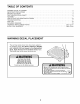
TABLE OF CONTENTS WARNING DECAL PLACEMENT .............................................................. IMPORTANT PRECAUTIONS ................................................................ BEFORE YOU BEGIN ...................................................................... PART IDENTIFICATION CHART .............................................................. ASSEMBLY ............................................................................... HOW TO USE THE VIBRATION PLATFORM ....................
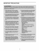
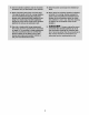
IMPORTANT PRECAUTIONS 3
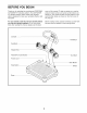
BEFORE YOU BEGIN Thank you for selecting the revolutionary PROFORM ® ACTIVATOR V7 vibration platform. The ACTIVATOR V7 vibration platform offers whole body vibration options designed to make tour workouts effective and enjoyable. cover of this manual. To help us assist you, note the product model number and serial number before contacting us. The model number and the location of the serial number decal are shown on the front cover of this manual.
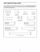
PART IDENTIFICATION CHART See the drawings below to identify small parts used in assembly, The number in parentheses by each drawing is the key number of the part, from the PART LIST near the end of this manual. Note: Some small parts may have been preattached. If a part is not in the hardware kit, check to see if it has been preattached. If a part is missing, call t-888-533-t333.
ASSEMBLY • For help identifying small parts, see the PART IDENTIFICATION CHART on page 6. • Tighten all parts as you assemble them, unless instructed to do otherwise. • Assembly may require the following tools (not included): Before beginning assembly, carefully read the following information and instructions: one adjustable wrench • Assembly requires two persons. one Phillips screwdriver one rubber mallet • Place all parts in a cleared area and remove the packing materials.
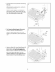
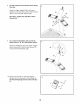
2. Tip: Be careful not to pinch the wires during this step. With the help of a second person, carefully tip the Base (5) onto its side. Attach the Lower Upright (1) to the Base (5) with two M10 x 55mm Patch Screws (20), two M10 Split Washers (38), two M10 x 68ram Bolts (55), and two M10 Nylon Locknuts (32). 20 38 3. Tip: Orient the Wheel Bracket (35) so that the arrow sticker is pointing upward. 28 Attach the Wheel Bracket (35) to the Lower Upright (1) with two M10 x 20mm Patch Screws (28). 4.
5. Attach the Weight Rest (42) to the Weight Rest Frame (41) with eight M5 x 38ram Screws (40). Do not tighten the Screws yet. 5 42 40 40 40 6, Locate the wire tie inside the Upper Upright (36). Insert the wire tie through the hole in the Weight Rest Frame (41). Next, attach the Upper Upright (36) to the Weight Rest Frame (41) with two M10 x 50ram Patch Screws (51) and two M!0 Split Washers (38). Wire Tie ,..__) Hole / 7, Have a second person hold the Upper Upright (36) near the Lower Upright (1).
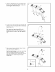
8. Tip: Be careful not to pinch the wires during this step. Attach the Upper Upright (36) to the Lower Upright (1) with four M10 x 20mm Patch Screws (28) and four M!0 Split Washers (38). 28 See step 5. Tighten the eight M5 x 38ram Screws (40). 28 9. Tip: Orient the Handlebar (39) so that the sticker with an "R" is in the location shown. Attach the Handlebar (39) to the Upper Upright (36) with two M10 x 62mm Patch Screws (37) and two M10 Split Washers (38). 10.
. Attach the back of the Console (3) to the Upper Upright (36) with two M4 x 16mm Patch Screws (26). Do not tighten the Screws yet. 11 3 26 12. While a second person holds the Front of the Console (3) near the Upper Upright (36), connect the console ground wire to the Ground Wire (52). Next, connect the console wire to the Wire Harness (43). Then, insert the wires into the Upper Upright. 12 13. Tip: Be careful not to pinch the wires during this step. 13 3_.
14. Set ten weight plates into the indicated slots in the right side of the Weight Rest (42). Next, lift the two selector pins on a Dumbbell (44), and slide the selector pins to the adjustment holes marked "2.5." Place the Dumbbell on the weight plates. Then, lift the two selector pins and slide them to the adjustment holes marked "15." 14 Selector ,Pins Repeat this step with the other Dumbbell (44). Weight 42 15. Plug the Power Cord (17) into the Receptacle (!8) located on the Base (5). 17 16.
HOW TO USE THE VIBRATION PLATFORM HOW TO MOVE THE VIBRATION PLATFORM Before moving the vibration platform, unplug the power cord and remove the dumbbells from the weight rest. Hold the handlebar and place one foot against the wheel. Tilt the vibration platform until it rolls freely on the wheel. Carefully move the vibration platform to the desired location. To reduce the risk of injury, use extreme caution while moving the vibration platform. Do not move the vibration platform over an uneven surface.
HOW TO PLUG IN THE POWER CORD This product is for use on a nominal 12g-volt circuit, and has a grounding plug that looks like the plug illustrated in drawing 1 below. Atemporary adapter that looks like the adapter illustrated in drawing 2 may be used to connect the surge suppressor to a 2-pole receptacle as shown in drawing 2 if a properly grounded outlet is not available. _Grounded _.
CONSOLE DIAGRAM f CONSOLE FEATURES you do not do this, the console or other electronic components may become damaged. The console offers a selection of features designed to make your workouts more effective and enjoyable. You can change the time and frequency of your vibration sessions with the touch of a button, Plug the power cord into the receptacle on the base of the vibration platform (see Position Reset assembly step 15 on page 12). Then, plug the power cord into a 120-volt outlet.
HOW TO USE THE MANUAL MODE HOW TO USE AN IFIT PROGRAM 1. 1. Turn on the power. Turn on the power. See HOW TO TURN ON THE POWER on page 15. 2. See HOW TO TURN ON THE POWER on page 15. Select the desired vibration time. 2. Press the desired time button to select a vibration To use an iFIT program, insert an iFIT card into the iFIT slot; make sure that the iFIT card is oriented so the metal contacts are face down and time of 30, 45, or 60 seconds.
TROUBLESHOOTING Inspect all parts of the vibration platform regularly. Replace any worn parts immediately. Outer surfaces of the vibration platform can be cleaned with a damp cloth and a mild, non-abrasive detergent; do not use solvents to clean the vibration platform. Most vibration platform problems can be solved by following the simple steps below. Find the symptom that applies, and follow the steps listed.
PART LIST--Model Key No. Qty. No. 831.14787.0 Description Ro4o8A Key No. Qty.
EXPLODED DRAWING-- Model No. 831.14787.
Your Home For repair--in or heating your home--of all major brand appliances, lawn and garden equipment, and cooling systems, no matter who made it, no matter who sold it! For the replacement parts, accessories, and user's manuals that you need to do-it-yourself. For Sears professional installation of home appliances and items like garage door openers and water heaters. 1-800-4-MY-HOME _ (1-800-469-4663) Call anytime, day or night (U.S.A. and Canada) www.sears.com www.