With Universal Dock for iPod® www.proform.com Model No. PFTL99908.2 Serial No. Write the serial number in the space above for reference. Serial Number Decal QUESTIONS? If you have questions, or if parts are damaged or missing, DO NOT CONTACT THE STORE; please contact Customer Care. IMPORTANT: Please register this product (see the limited warranty on the back cover of this manual) before contacting Customer Care. 1-888-533-1333 CALL TOLL-FREE: Mon.–Fri. 6 a.m.–6 p.m. MT Sat. 8 a.m.–4 p.m.
TABLE OF CONTENTS WARNING DECAL PLACEMENT . . . . . . . . . . . . . . . . . . . . . . . . . . . . . . . . . . . . . . . . . . . . . . . . . . . . . . . . . . . . . .2 IMPORTANT PRECAUTIONS . . . . . . . . . . . . . . . . . . . . . . . . . . . . . . . . . . . . . . . . . . . . . . . . . . . . . . . . . . . . . . . .3 BEFORE YOU BEGIN . . . . . . . . . . . . . . . . . . . . . . . . . . . . . . . . . . . . . . . . . . . . . . . . . . . . . . . . . . . . . . . . . . . . . .5 ASSEMBLY . . . . . . . . . . . . .
IMPORTANT PRECAUTIONS WARNING: To reduce the risk of serious injury, read all important precautions and instructions in this manual and all warnings on your treadmill before using your treadmill. ICON assumes no responsibility for personal injury or property damage sustained by or through the use of this product. 1. Before beginning any exercise program, consult your physician. This is especially important for persons over age 35 or persons with pre-existing health problems. of carrying 15 or more amps.
24. Inspect and properly tighten all parts of the treadmill regularly. 20. Never leave the treadmill unattended while it is running. Always remove the key, unplug the power cord, and switch the reset/off circuit breaker to the off position when the treadmill is not in use. (See the drawing on page 5 for the location of the circuit breaker.) 25. 21. Do not attempt to raise, lower, or move the treadmill until it is properly assembled.
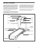
BEFORE YOU BEGIN Thank you for selecting the revolutionary PROFORM® 980 CS treadmill with Universal Dock for iPod®. The 980 CS treadmill with Universal Dock for iPod offers an impressive selection of features designed to make your workouts at home more enjoyable and effective. And when youʼre not exercising, the unique treadmill can be folded up, requiring less than half the floor space of other treadmills. ing this manual, please see the front cover of this manual.
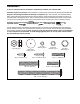
ASSEMBLY To hire an authorized service technician to assemble the treadmill, call 1-800-445-2480. Assembly requires two persons. Set the treadmill in a cleared area and remove all packing materials. Do not dispose of the packing materials until assembly is completed. Note: The underside of the treadmill walking belt is coated with high-performance lubricant. During shipping, some lubricant may be transferred to the top of the walking belt or the shipping carton.
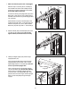
1. Make sure that the power cord is unplugged. 1 With the help of a second person, carefully tip the treadmill onto its left side. Partially fold the Frame (56) so that the treadmill is more stable; do not fully fold the Frame yet. 38 83 Hole 81 Cut the ties securing the Upright Wire (38) to the Base (83). Locate the tie in the indicated hole in the Base, and use the tie to pull the Upright Wire out of the hole.
4. Hold a Bolt Spacer (77) inside the lower end of the Right Upright (78). Next, insert a 3/8" x 4 1/2" Bolt (6) with a 3/8" Star Washer (9) into the Right Upright and the Bolt Spacer. Repeat this step with a second Bolt Spacer (77), 3/8" x 4 1/2" Bolt (6), and 3/8" Star Washer (9). Then, set the Right Upright in the Right Upright Spacer (79). Be careful not to pinch the Upright Wire (38). 4 6 78 9 79 38 Partially tighten the 3/8" x 4 1/2" Bolts (6); do not fully tighten the Bolts yet. 77 5.
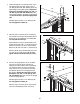
7. Set the console assembly face down on a soft surface to avoid scratching the console assembly. 7 Hold the Right Handrail (95) near the console assembly. Next, insert the console wire into the large hole in the Right Handrail and out of the top as shown. If necessary, use needlenose pliers to pull the console wire out. Console Wire Hole 95 Attach the Right Handrail (95) and the Left Handrail (not shown) with four #8 x 3/4" Screws (1) (only two are shown). Make sure that no wires are pinched.
. Attach the console assembly with six 5/16" x 1 1/2" Bolts (7) and six 5/16" Star Washers (10) (only three are shown). 10 Console Assembly See steps 4 and 6. Tighten the 3/8" x 4 1/2" Bolts (6). 7 11. Raise the Frame (56) to the position shown. Have a second person hold the Frame until this step is completed. 11 Orient the Storage Latch (53) so that the large barrel and the Latch Knob (54) are in the positions shown.
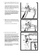
12. Press the Left Accessory Tray (99) and the Right Accessory Tray (97) into the console assembly. 12 99 Console Assembly 97 13. Make sure that all parts are properly tightened before you use the treadmill. If there are sheets of clear plastic on the treadmill decals, remove the plastic. To protect the floor or carpet, place a mat under the treadmill. Note: Extra hardware may be included.
OPERATION AND ADJUSTMENT THE PRE-LUBRICATED WALKING BELT tric shock. This product is equipped with a cord having an equipment-grounding conductor and a grounding plug. Plug the power cord into a surge suppressor, and plug the surge suppressor into an appropriate outlet that is properly installed and grounded in accordance with all local codes and ordinances. IMPORTANT: The treadmill is not compatible with GFCI-equipped outlets. Your treadmill features a walking belt coated with highperformance lubricant.
CONSOLE DIAGRAM Navigation Buttons Key FEATURES OF THE CONSOLE The revolutionary treadmill console offers a selection of features designed to make your workouts more effective and enjoyable. When you use the manual mode of the console, you can change the speed and incline of the treadmill with the touch of a button. As you exercise, the console will display continuous exercise feedback.
HOW TO TURN ON THE POWER IMPORTANT: If the treadmill has been exposed to cold temperatures, allow it to warm to room temperature before turning on the power. If you do not do this, you may damage the console displays or other electrical components. Plug in the power cord (see page 12). Next, locate the reset/off circuit breaker on the treadmill frame near the power cord. Switch the circuit breaker to the reset position.
6. Follow your progress with the display. The console offers several display options. The display option you select will determine which workout information is shown. Press the Display button repeatedly to select the desired display option. 7. Measure your heart rate if desired. If you hold the handgrip pulse sensor and wear the optional chest pulse sensor at the same time, the console will not display your heart rate accurately. See page 23 for information about the optional chest pulse sensor.
HOW TO USE A WEIGHT LOSS WORKOUT OR A PERFORMANCE WORKOUT sents the current segment of the program. The height of the flashing segment indicates the speed setting for the current segment. At the end of each segment, a series of tones will sound and the next segment of the profile will begin to flash and the speed and incline setting will appear in the display to alert you. The speed and incline will automatically adjust to the speed and incline settings programmed for the next segment. 1.
HOW TO USE AN IFIT CARD 3. Press the Start button to start the workout. To purchase iFit cards at any time, call the telephone number on the front cover of this manual or go to www.iFit.com. iFit cards are also available at select stores. A moment after you press the Start button, the treadmill will automatically adjust to the first speed and incline settings of the workout. Hold the handrails and begin walking. 1. Insert the key into the console.
HOW TO USE THE IFIT COMPETITION TRAINING CENTER select a profile of the incline settings of the race (see page 20). 1. Insert the key into the console. After a few moments, READY, SET, GO will appear in the display and then the race will begin. Hold the handrails and begin walking. See HOW TO TURN ON THE POWER on page 14. Adjust the speed and incline of the treadmill as desired. Your opponents will adjust their speed and tactics based on the course and the situation. 2.
• The speed of the walking belt. Note: Press the Enter button to see your pace in minutes per kilometer or minutes per mile. Press the Enter button again to view the speed of the walking belt. • The bank, or amount, of energy your opponents have left. As the amount of energy in a bank decreases, the speed of that opponent will decrease. • The incline level of the treadmill. • The racing tactics your opponents are using. Your opponents will use different tactics in different situations.
HOW TO PERSONALIZE CONSOLE SETTINGS workout. If you change the maximum incline setting, the intensity of the entire workout will change. Choose the AUTO incline mode to use preset incline settings, the FLAT incline mode to use no incline settings, or the CHOICE incline mode to choose a profile of the incline settings at the beginning of a competition workout. If you change the start speed, the walking belt will begin moving at the selected speed whenever a competition workout begins. 1.
HOW TO VIEW THE FITNESS JOURNAL change the year. Note: The fitness journal can store information for 7 different years. You can only view a year for which information has been recorded. 1. Insert the key into the console. See HOW TO TURN ON THE POWER on page 14. 4. View exercise information by month. 2. Select the fitness journal. After a few seconds, the view month menu will appear in the display. To select the fitness journal, press the iFit Fitness Journal button.
THE INFORMATION MODE The console features an information mode that allows you to select a unit of measurement for the console and turn on or turn off the display demo mode. You can also set the date and time. To select the information mode, hold down the Stop button, insert the key into the console, and then release the Stop button. When the information mode is selected, the following information will appear in the display: The display will show the selected unit of measurement.
THE OPTIONAL CHEST PULSE SENSOR An optional chest pulse sensor offers hands-free operation as it tracks your heart rate during your workouts. To purchase the optional chest pulse sensor, call the telephone number on the front cover of this manual. HOW TO ADJUST THE CUSHIONING SYSTEM Remove the key from the console and unplug the power cord. The treadmill features a cushioning system that reduces the impact as you walk or run on the treadmill.
HOW TO FOLD AND MOVE THE TREADMILL HOW TO FOLD THE TREADMILL FOR STORAGE Before folding the treadmill, adjust the incline to the lowest position. If you do not do this, you may damage the treadmill when you fold it. Remove the key and unplug the power cord. CAUTION: You must be able to safely lift 45 lbs. (20 kg) to raise, lower, or move the treadmill. 1. Hold the metal frame firmly in the location shown by the arrow at the right.
HOW TO LOWER THE TREADMILL FOR USE 1. Hold the upper end of the treadmill with your right hand. Pull the latch knob to the left and hold it. It may be necessary to push the frame forward as you pull the knob to the left. Pivot the frame downward and release the latch knob. Frame Latch Knob 2. Hold the metal frame firmly with both hands and lower it to the floor. CAUTION: Do not grip only the plastic foot rails or drop the frame to the floor. Bend your legs and keep your back straight.
TROUBLESHOOTING Most treadmill problems can be solved by following the steps below. Find the symptom that applies, and follow the steps listed. If further assistance is needed, please see the front cover of this manual. PROBLEM: The power does not turn on SOLUTION: a. Make sure that the power cord is plugged into a surge suppressor, and that the surge suppressor is plugged into a properly grounded outlet (see page 12).
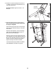
Remove the three #8 x 3/4" Screws (1) and carefully pivot the Hood (61) off. 61 Locate the Reed Switch (71) and the Magnet (50) on the left side of the Pulley (51). Turn the Pulley until the Magnet is aligned with the Reed Switch. Make sure that the gap between the Magnet and the Reed Switch is about 1/8 in. (3 mm). If necessary, loosen the 3/4" Reed Switch Screw (15), move the Reed Switch slightly, and then retighten the Screw. Reattach the Hood (not shown) with the #8 x 3/4" Screws (not shown).
PROBLEM: The walking belt is off-center or slips when walked on SOLUTION: a. If the walking belt is off-center, first remove the key and UNPLUG THE POWER CORD. If the walking belt has shifted to the left, use the hex key to turn the left rear roller bolt clockwise 1/2 of a turn; if the walking belt has shifted to the right, turn the bolt counterclockwise 1/2 of a turn. Be careful not to overtighten the walking belt. Then, plug in the power cord, insert the key, and run the treadmill for a few minutes.
EXERCISE GUIDELINES WARNING: Before beginning this Burning Fat—To burn fat effectively, you must exercise at a low intensity level for a sustained period of time. During the first few minutes of exercise, your body uses carbohydrate calories for energy. Only after the first few minutes of exercise does your body begin to use stored fat calories for energy. If your goal is to burn fat, adjust the intensity of your exercise until your heart rate is near the lowest number in your training zone.
PART LIST—Model No. PFTL99908.2 To locate the parts listed below, see the EXPLODED DRAWING near the end of this manual. Key No. Qty. 1 2 3 4 5 6 7 8 9 10 11 12 13 14 15 16 17 18 19 20 21 22 23 24 25 26 27 28 29 30 31 32 33 34 35 36 37 38 39 40 41 42 43 44 45 46 47 48 49 50 25 4 1 6 2 4 6 8 4 6 5 4 2 1 1 12 2 2 2 2 1 1 2 8 10 2 2 1 10 2 2 2 2 4 1 2 3 1 1 2 1 1 2 1 1 2 2 2 1 1 Description Key No. Qty.
Key No. Qty. 101 102 103 104 1 2 1 1 Description Key No. Qty. Console Ground Wire #8 x 2" Screw 5/32" Hex Key Lift Motor Spacer 105 * * * 1 – – – Description Latch Endcap 4" Black Wire, M/F 4" White Wire, M/F Userʼs Manual Note: Specifications are subject to change without notice. For information about ordering replacement parts, see the back cover of this manual. *These parts are not illustrated.
20 31 25 30 57 16 24 103 34 59 36 58 3 18 42 16 25 20 16 41 31 60 30 25 24 18 44 47 27 63 16 43 29 34 80 57 36 46 40 12 16 45 25 25 16 48 55 8 16 17 51 4 54 47 27 63 25 16 43 50 56 53 29 25 17 46 40 49 12 25 8 48 105 4 EXPLODED DRAWING A—Model No. PFTL99908.
EXPLODED DRAWING B—Model No. PFTL99908.
EXPLODED DRAWING C—Model No. PFTL99908.
EXPLODED DRAWING D—Model No. PFTL99908.
ORDERING REPLACEMENT PARTS To order replacement parts, please see the front cover of this manual.