
User`s manual


9
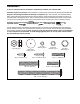
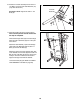
7. Set the console assembly face down on a soft
surface to avoid scratching the console assem-
bly.
H
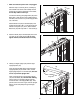
old the Right Handrail (95) near the console
assembly. Next, insert the console wire into the
large hole in the Right Handrail and out of the
top as shown. If necessary, use needlenose pli-
e
rs to pull the console wire out.
Attach the Right Handrail (95) and the Left
Handrail (not shown) with four #8 x 3/4" Screws
(1) (only two are shown). Make sure that no
wires are pinched. Start all four Screws be-
fore tightening any of them; do not over-
tighten the Screws.
95
1
Console
W
ire
Hole
1
7
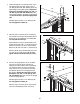
8. Tighten a 1/4" x 1 1/4" Bolt (5) with a 1/4" Star
Washer (33) into the Handrail Crossbar (94) and
the bracket on each side of the console assembly
(only one side is shown).
Remove the wire tie from the console wire.
5
33
94
Console
Assembly
Wire
Tie
8
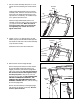
9. Remove the tie from the Cage Nut (88).
Have a second person hold the console assem-
bly near the Right Upright (78) and the Left
Upright (not shown). Connect the Upright Wire
(38) to the console wire. See the inset drawing.
The connectors should slide together easily
and snap into place. If they do not, turn one
connector and try again. IF THE CONNECTORS
ARE NOT CONNECTED PROPERLY, THE
CONSOLE MAY BE DAMAGED WHEN THE
POWER IS TURNED ON. Then, remove the long
tie from the Upright Wire.
Set the console assembly on the Right Upright
(78) and the Left Upright (not shown). Be care-
ful not to pinch the wires.
Console
Assembly
Console
Wire
Long
Tie
38
78
88
9
38
Console
Assembly
Console
Wire
Console
Wire