www.proform.com Model No. PFEL01415.2 Serial No. Write the serial number in the space above for reference. Serial Number Decal ACTIVATE YOUR WARRANTY To register your product and activate your warranty today, go to www.proformservice.com/ registration. CUSTOMER CARE For service at any time, go to www.proformservice.com. Or call 1-888-533-1333 Mon.–Fri. 6 a.m.–6 p.m. MT Sat. 8 a.m.–12 p.m. MT Please do not contact the store.
TABLE OF CONTENTS WARNING DECAL PLACEMENT . . . . . . . . . . . . . . . . . . . . . . . . . . . . . . . . . . . . . . . . . . . . . . . . . . . . . . . . . . . . . . .2 IMPORTANT PRECAUTIONS. . . . . . . . . . . . . . . . . . . . . . . . . . . . . . . . . . . . . . . . . . . . . . . . . . . . . . . . . . . . . . . . . . 3 BEFORE YOU BEGIN. . . . . . . . . . . . . . . . . . . . . . . . . . . . . . . . . . . . . . . . . . . . . . . . . . . . . . . . . . . . . . . . . . . . . . . .7 PART IDENTIFICATION CHART.
IMPORTANT PRECAUTIONS WARNING: To reduce the risk of burns, fire, electric shock, or injury to persons, read all important precautions and instructions in this manual and all warnings on your trainer before using your trainer. ICON assumes no responsibility for personal injury or property damage sustained by or through the use of this product. 1. It is the responsibility of the owner to ensure that all users of the trainer are adequately informed of all precautions. 10.
18. The trainer does not have a freewheel; the pedals will continue to move until the flywheel stops. Reduce your pedaling speed in a controlled way. 20. Over exercising may result in serious injury or death. If you feel faint, if you become short of breath, or if you experience pain while exercising, stop immediately and cool down. 19. Keep your back straight while using the trainer; do not arch your back.
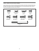
UTS STANDARD SERVICE PLANS all 6
BEFORE YOU BEGIN Thank you for selecting the revolutionary PROFORM® CARDIO HIIT PRO TRAINER. The CARDIO HIIT PRO TRAINER trainer provides an impressive selection of features designed to make your workouts at home more effective and enjoyable. reading this manual, please see the front cover of this manual. To help us assist you, note the product model number and serial number before contacting us. The model number and the location of the serial number decal are shown on the front cover of this manual.
PART IDENTIFICATION CHART Use the drawings below to identify the small parts needed for assembly. The number in parentheses below each drawing is the key number of the part, from the PART LIST near the end of this manual. The number following the key number is the quantity needed for assembly. Note: If a part is not in the hardware kit, check to see if it has been preassembled. Extra parts may be included.
ASSEMBLY • To hire an authorized service technician to assemble this product, call 1-800-445-2480. • To identify small parts, see page 8. • In addition to the included tool(s), assembly requires the following tools: • Assembly requires two persons. one Phillips screwdriver • Place all parts in a cleared area and remove the packing materials. Do not dispose of the packing materials until you finish all assembly steps. Assembly may be easier if you have your own set of wrenches.
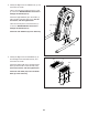
2. Identify the Right and Left Stabilizers (8, 9), and orient them as shown. 2 Have a second person hold the Frame (1) and tip it to the left. IMPORTANT: Be careful not to damage the Shields (50, 51). Attach the Right Stabilizer (8) to the Frame (1) with four M10 x 20mm Screws (110); start all the Screws, and then tighten them. Have the second person lower the Frame (1) to the floor. IMPORTANT: Be careful not to damage the Shields (50, 51). 50, 51 9 Attach the Left Stabilizer (9) in the same way.
4. Attach the Right Pedal Base (2) to the Right Pedal Leg (24) with four M8 x 20mm Screws (102); start all the Screws, and then tighten them. 4 Attach the Left Pedal Base (not shown) to the Left Pedal Leg (not shown) in the same way. 102 24 102 2 5. Press the Rear Cover (53) onto the Left and Right Shields (50, 51). 5 18 Attach the Rear Cover (53) with four M4 x 16mm Flat Head Screws (101); start all the Flat Head Screws, and then tighten them.
6. See the upper drawing. With the help of a second person, orient the Console (5), the Console Cover (7), and the Console Bracket (4) as shown. Route the wires (A) on the Console through the Console Cover and the Console Bracket as shown; make sure to insert the wires through the upper part of the hole in the Console Bracket. 6 5 See the lower drawing. Tip: Avoid pinching the wires.
8. While a second person holds the Console Bracket (4) near the Frame (1), connect the wires on the Console to the Main Wire (115) and to the Left and Right Pulse Wires (117, 125). 8 Avoid pinching the wires Tip: Avoid pinching the wires. Attach the Console Bracket (4) to the Frame (1) with two M8 x 86mm Screws (109) and two M8 x 15mm Screws (96); start all the Screws, and then tighten them. 117, 125 109 4 115 96 96 1 9. Identify the Right and Left Handlebars (10, 11).
10. Identify the Rear and Front Pivot Covers (65, 66). 10 Press a set of Rear and Front Pivot Covers (65, 66) together around the Right Handlebar (10) near the bend (A). Then, attach them to each other with two M4 x 22mm Screws (107). 10 See the inset drawing. Slide the Rear and Front Pivot Covers (65, 66) toward the Shield Cover (12). Attach the Front Pivot Cover to the Right Handlebar (10) with an M4 x 22mm Screw (107). 66 65 A Repeat this step on the other side of the trainer. 65 10 11.
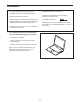
THE CHEST HEART RATE MONITOR HOW TO PUT ON THE HEART RATE MONITOR • Store the heart rate monitor in a warm, dry place. Do not store the heart rate monitor in a plastic bag or other container that may trap moisture. If the heart rate monitor looks like the one shown in drawing 1, press the transmitter (A) onto the snap fasteners on the chest strap (B). If the heart rate monitor looks like the one shown in drawing 2, insert the tab (C) on one end of the chest strap (D) into one end of the transmitter (E).
HOW TO USE THE TRAINER HOW TO PLUG IN THE POWER CORD A temporary adapter may be used to connect the power cord to a 2-pole receptacle as shown at the right if a properly grounded outlet is not available. This product must be grounded. If it should malfunction or break down, grounding provides a path of least resistance for electric current to reduce the risk of electric shock. The power cord has a plug with a grounding pin.
HOW TO MOVE THE TRAINER HOW TO EXERCISE ON THE TRAINER Due to the size and weight of the trainer, moving it requires two persons. Stand in front of the trainer, hold the console bracket, and place one foot against one of the wheels. Have a second person help you pull on the console bracket until the trainer will roll on the wheels. Carefully move the trainer to the desired location, and then lower it to the floor.
HOW TO LEVEL THE TRAINER HOW TO USE THE TABLET HOLDER If the trainer rocks slightly on your floor during use, turn one or both of the leveling feet beneath the stabilizers until the rocking motion is eliminated. IMPORTANT: The tablet holder is designed for use with most full-size tablets. Do not place any other electronic device or object in the tablet holder. To insert a tablet into the tablet holder, set the bottom edge of the tablet in the tray. Then, pull the clip over the top edge of the tablet.
CONSOLE DIAGRAM MAKE YOUR FITNESS GOALS A REALITY WITH IFIT.COM Upload your workout results to the iFit cloud and track your accomplishments. With your new iFit-compatible fitness equipment, you can use an array of features on iFit.com to make your fitness goals a reality: Set calorie, time, or distance goals for your workouts. Exercise anywhere in the world with customizable Google Maps. Watch high-definition videos with simulated workouts.
FEATURES OF THE CONSOLE HOW TO TURN ON THE POWER The advanced console offers an array of features designed to make your workouts more effective and enjoyable. IMPORTANT: If the trainer has been exposed to cold temperatures, allow it to warm to room temperature before you turn on the power. If you do not do this, you may damage the console displays or other electrical components. The console features revolutionary iFit technology that enables the console to communicate with your wireless network.
HOW TO USE THE TOUCH SCREEN 2. Check for firmware updates. The console features a tablet with a full-color touch screen. The following information will help you become familiar with the tablet’s advanced technology: First, see step 1 and 2 on page 29 and select the maintenance mode. Then, see step 3 on page 29 and check for firmware updates. • The console functions similarly to other tablets.
HOW TO USE THE MANUAL MODE If desired, adjust the volume level by pressing the Vol increase and decrease buttons on the console or by pressing the Volume increase and decrease buttons on the left grip. 1. Touch the screen or press any button on the console to turn on the console. See HOW TO TURN ON THE POWER on page 20. 2. Select the main menu. To pause the workout, touch one of the menu buttons on the screen. To continue the workout, touch the Resume button.
If the display does not show your heart rate, make sure that your hands are positioned as described. Be careful not to move your hands excessively or to squeeze the contacts tightly. For optimal performance, clean the contacts using a soft cloth; never use alcohol, abrasives, or chemicals to clean the contacts. HOW TO USE AN ONBOARD WORKOUT 6. Turn on the fan if desired. 2. Select the main menu. The fan has several speed settings, including an auto mode.
As you exercise, keep your pedaling speed near the target cadence for the current segment. The target zone meter will prompt you to increase, decrease, or maintain your pedaling speed. To view the target zone meter, flick or slide the screen. Note: The target cadence is displayed in revolutions per minute (rpm). To pause the workout, touch either the back button or the home button at the bottom of the screen. To continue the workout, touch the Resume button.
HOW TO USE A SET-A-GOAL WORKOUT If the resistance level for the current segment is too high or too low, you can manually override the setting by pressing the Resistance buttons. If you press a Resistance button, you can then manually control the resistance (see step 3 on page 22). To return to the programmed resistance settings of the workout, touch the Follow Workout button. 1. Begin pedaling or press any button on the console to turn on the console. See HOW TO TURN ON THE POWER on page 20. 2.
HOW TO USE AN IFIT WORKOUT Wt. button. The next workout of that type in your schedule will then download. Note: You may be able to access demo workouts through these buttons, even if you do not log in to your iFit account. To use an iFit workout, the console must be connected to a wireless network (see HOW TO USE THE WIRELESS NETWORK MODE on page 30). An iFit account is also required. To compete in a race or challenge that you have previously joined on iFit.com, touch the Compete button.
HOW TO USE THE EQUIPMENT SETTINGS MODE 6. Turn on or turn off the display demo mode. IMPORTANT: Some of the features described may not be enabled. Occasionally, a firmware update may cause your console to function slightly differently. 1. Select the settings main menu. The console features a display demo mode, designed to be used if the trainer is displayed in a store. While the demo mode is turned on, the screen will show a preset presentation when the trainer is not in use.
Note: If a passcode is enabled, the console will regularly ask for you to enter the passcode. The console will remain locked until the correct passcode is entered. IMPORTANT: If you forget your passcode, enter the following master passcode to unlock the console: 1985. desired time. Then, touch the back button on the screen. When you select an update time, you must also enable automatic console updates (see step 4). IMPORTANT: You must still unplug the power cord after using your trainer.
HOW TO USE THE MAINTENANCE MODE Note: Occasionally, a firmware update may cause your console to function slightly differently. These updates are always designed to improve your exercise experience. IMPORTANT: Some of the features described may not be enabled. Occasionally, a firmware update may cause your console to function slightly differently. 4. View machine information. 1. Select the settings main menu. Touch the Machine Info button to view information about your trainer.
HOW TO USE THE WIRELESS NETWORK MODE name (SSID). If your network has a password, you will also need to know the password. The console features a wireless network mode that allows you to set up a wireless network connection. An information box will ask if you want to connect to the wireless network. Touch the Connect button to connect to the network or touch the Cancel button to return to the list of networks. If the network has a password, touch the password entry box.
HOW TO USE THE SOUND SYSTEM HOW TO USE THE INTERNET BROWSER To play music or audio books through the console sound system while you exercise, plug a 3.5 mm male to 3.5 mm male audio cable (not included) into the jack on the console and into a jack on your personal audio player; make sure that the audio cable is fully plugged in. Note: To purchase an audio cable, see your local electronics store.
FCC INFORMATION This equipment has been tested and found to comply with the limits for a Class B digital device, pursuant to part 15 of the FCC Rules. These limits are designed to provide reasonable protection against harmful interference in a residential installation. This equipment generates, uses, and can radiate radio frequency energy and, if not installed and used in accordance with the instructions, may cause harmful interference to radio communications.
MAINTENANCE AND TROUBLESHOOTING MAINTENANCE HOW TO ADJUST THE REED SWITCH Regular maintenance is important for optimal performance and to reduce wear. Inspect and properly tighten all parts each time the trainer is used. Replace any worn parts immediately. If the console does not display correct feedback, the reed switch should be adjusted. To adjust the reed switch, first unplug the power adapter. Next, remove the four indicated M4 x 16mm Flat Head Screws (101) and the Lower Rear Shield Cover (68).
HOW TO ADJUST THE DRIVE BELT Then, locate the lower Adjustment Screw (A). Tighten the lower Adjustment Screw four turns; this will tighten the Large Drive Belt (31). If the pedals slip while you are pedaling, even while the resistance is adjusted to the highest level, the drive belts may need to be adjusted. To adjust the drive belts, first unplug the power adapter. Next, remove the four indicated M4 x 16mm Flat Head Screws (101) and the Lower Rear Shield Cover (68).
EXERCISE GUIDELINES Burning Fat—To burn fat effectively, you must exercise at a low intensity level for a sustained period of time. During the first few minutes of exercise, your body uses carbohydrate calories for energy. Only after the first few minutes of exercise does your body begin to use stored fat calories for energy. If your goal is to burn fat, adjust the intensity of your exercise until your heart rate is near the lowest number in your training zone.
PART LIST Key No. Qty. 1 2 3 4 5 6 7 8 9 10 11 12 13 14 15 16 17 18 19 20 21 22 23 24 25 26 27 28 29 30 31 32 33 34 35 36 37 38 39 40 41 42 43 44 45 46 47 48 49 50 1 1 1 1 1 1 1 1 1 1 1 1 2 1 1 1 2 1 1 1 1 1 1 1 1 2 1 1 2 1 1 2 2 1 2 1 1 1 1 1 1 1 3 2 2 1 1 1 2 1 Model No. PFEL01415.2 R0117A Description Key No. Qty.
Key No. Qty. 101 102 103 104 105 106 107 108 109 110 111 112 113 114 115 116 117 14 8 18 2 6 16 10 8 2 8 4 1 25 15 1 1 1 Description Key No. Qty.
77 71 108 120 23 87 84 131 35 79 3 102 73 87 108 79 100 130 84 71 91 73 78 87 38 25 32 70 89 93 85 33 78 120 119 85 26 88 70 92 129 73 31 78 41 43 27 1 21 30 121 74 95 2 94 113 116 17 108 42 72 76 70 96 75 95 70 106 43 121 122 22 29 90 87 14 72 74 40 29 43 89 90 100 100 17 36 85 71 28 73 4 79 84 24 77 87 70 26 78 112 78 129 87 88 100 130 33 113 131 88 32 84 12 107 106 13 79 70 87 111 97 98 6 73 35 34 128
55 101 83 18 113 54 101 53 123 101 9 68 101 106 56 114 113 103 113 81 113 113 46 101 113 57 103 114 103 45 110 99 110 114 83 106 56 101 44 114 114 83 69 103 48 60 83 49 55 83 83 83 113 113 69 8 113 110 110 82 82 113 83 101 113 50 61 59 105 67 82 106 110 56 113 81 66 58 103 117 10 103 44 125 47 59 103 63 107 49 104 99 113 57 56 103 113 106 113 82 101 51 65 52 65 106 104 11 62 105 118 67 64 106 115 107 66 60
ORDERING REPLACEMENT PARTS To order replacement parts, please see the front cover of this manual.