
Instructions / Assembly


10
6
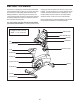
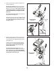
6. Have a second person hold the Handlebar (5)
near the Upright (4).
See the inset drawing. Route the Upper Wire
(87) through the Pivot Post (78) and the Pivot
Bracket (71) as shown. Tip: It may be easier to
route the Upper Wire if you adjust the angle
of the Pivot Bracket by turning the Console
Knob (77).
Tip: Avoid pinching the wires. Insert the Pivot
Post (78) into the Upright (4).
Attach the Pivot Post (78) to the Upright (4) with
two M8 x 50mm Bolts (70) and two M8 Locknuts
(43); make sure that the Locknuts are in the
hexagonal holes.
4
71
43
70
78
77
87
71
78
5
Hexagonal
Holes
Avoid pinching
the wires
7
87
61
13
72
71
72
72
77
Avoid pinching
the wires
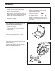
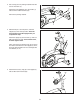
7. While a second person holds the Console (13)
near the Pivot Bracket (71), connect the wires
on the Console to the Upper Wire (87) and the
Pulse Wires (61).
Insert the excess wire downward through the
Pivot Bracket (71). Do not insert the excess
wire into the Console (13); the wires may
interfere with the fan.
Tip: Avoid pinching the wires. Attach the
Console (13) to the Pivot Bracket (71) with four
M4 x 16mm Screws (72). Tip: It may be help-
ful to adjust the angle of the Pivot Bracket by
turning the Console Knob (77).
87