
User Manual


ProgressiveIndustries.net | 919-267-6964
5
INSTRUCTION MANUAL:
ELECTRICAL MANAGEMENT SYSTEM (EMS)
10) Secure cable ends by tightening down strain reliefs ove the input and output wires.
Do not over tighten as this could bit through the insulation and cause a short.
11) Set time delay jumper on the circuit board. The factory setting is for 15 seconds.
Remove jumper to set for 136 seconds (02:16). See Features Section on time delay
to determine which to use.
12) Plug in remote display and cable. (This cable is not a phone cable, but rather a data
cable). NEVER PLUG IN DISPLAY WHILE RV POWER IS ON.
13) Attach EMS lid with the six black machine screws provided.
14) Mount the EMS control box.
15) Installation is complete. Next, plug in and follow operating instructions.
Visual Photo Library - LCHW50C: page 9 | LCHW30C: page 10
Wiring Diagram - LCHW50C: page 11 | LCHW30C: page 11
For installation, in addition to the EMS Kit, you will need:
• 4 mounting screws
• In some cases you will need a jumper cable, length to be determined
based on the placement of the EMS.
• Always use #10 wire for LCHW30 models and #6 wire for LCHW50 models.
• Surge & Electrical Protection units are for Recreational Vehicles (RV) only.
1) Unplug RV from the AC power and be sure generator is o.
2) Locate transfer switch box; determine where the EMS control box will be mounted.
3) Measure the distance between the transfer switch and the control box and add one
(1) foot. This is the length of cable that will be required for the installation. Make
sure 6 gauge, 4 conductor cables are used.
4) Remove lid from transfer box, disconnect and remove the output cable.
5) Take jumper cable and strip back one end three (3) inches and the other end the
same as the end removed from the transfer box. The cable removed from the
transfer box must have at least three (3) inches of the outer insulation removed.
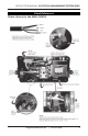
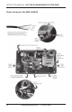
See visual references on page 9.
6) Strip back all conductors 3/8" and attach ring terminals to green ground wires (see
visual references on page 9). If this wire is solid wire, do not use ring terminals.
Loop the wire around the screw.
7) Remove the lid from unit. Inside the unit will be a digital display, cable and pack of
screws. Back o the six set screws from top of contactor (L1, L2, etc.).
Installation After Transfer Box for Protection
from both Generator and AC Power