
User Manual


ProgressiveIndustries.net | 919-267-6964
6
INSTRUCTION MANUAL: ELECTRICAL MANAGEMENT SYSTEM (EMS)
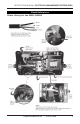
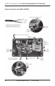
8) Take the jumper cable and connect it to the input side by sliding through the wire
restraint on the end of the EMS control box and then connect the black wire to L1;
white to L2; red to L3, green to ground screw. See visual references on page 9.
Torque down set screws and ground nut to secure connections.
9) The cable that came from the transfer box connects to the output side of the EMS
control box in the same manner. Next slide the black wire through the current
sensor containing the green tape and connect to T1 and then connect the white
wire to T2. Now slide the red wire through the other current sensor and attach to
T3. The arrow side o the sensor needs to face T1 and T3. Next, attach the green
ground wire to the ground screw on the side of box (see visual references on page
9). Make sure the conductor’s colors match up across from each other. Torque
down the set screws and ground nut to secure connections.
10) Connect the loose end of the jumper cable to the transfer switch. See wiring
diagram on transfer switch if needed.
11) Double check all connections to ensure they are secure.
12) Secure cable ends by tightening down strain reliefs over the input and output
wires. Do not over tighten as this could bite through insulation and cause a short.
13) Set time delay jumper on the circuit board. Factory setting is for 15 seconds.
Remove jumper to change setting to 136 seconds (02:16). See Features Section on
time delay to determine which to use. See visual references on page 9.
14) Plug in digital remote and data cable (this cable is not a phone cable, but rather a
data cable). NEVER PLUG IN THE DISPLAY WHILE RV POWER IS ON.
15) Attach lid with the six black machine screws provided and attach transfer switch lid.
16) Mount the EMS control box.
17) Installation is complete. Next, plug in and follow operating instructions.
Operating Instructions
1) Plug into A/C power.
2) Digital display will read 888 for one second and then begin scrolling the voltage,
amps, line frequency and error code, if any. In addition, the time delay light will
ash while the EMS is going through its countdown and will stop when the unit
engages (bottom right hand corner.) If delay light does not ash, a fault condition
is present. Refer to the Error Code Chart (page 7) to determine the problem
with the AC power.
3) You may notice when rst plugging in, the display may read E 9. This indicates the
display has not received the data from the computer yet. Do not be alarmed, this
is normal. By the next scroll through, it should read E 0 if the AC power is normal.