
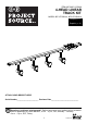
Installation Guide

7
9
G
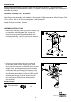
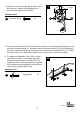
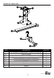
9. To remove the track head (G) from the track
section (F), first allow the track head (G) to cool
down. Pull down on the track head (G)
connector’s locking tab, and twist until the
track head (G) disengages.
F
GROUND
TAB
GROUND GROOVE
GROUND SIDE OF
CONNECTOR
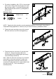
8. Identify ground side on the track head (G)
connector and track section (F). Push the top
portion of the track head (G) connector into the
slot of the track section (F). Pull down the
connector’s locking tab. Twist ground side of
the track head (G) connector toward the ground
side the track section (F) until the track head (G)
connector snaps into place.
NOTE: The ground side of the track head (G)
connector is the side with two metal tabs. The
ground side of the track section (F) has an indented
groove on the face and two internal copper
strips. The track head (G) can only be
assembled if the ground sides of the track
head (G) connector and the track section (F)
are aligned.
8
G
F
7
G
H
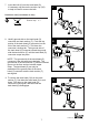
7. Insert the bulb (H) into the track head (G).
If necessary may be use the suction cup (GG)
to help to install or remove the bulb.
GG
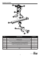
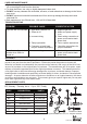
Hardware used (not shown to size)
GG
Suction cup x 1
Lowes.com