
Manual


11
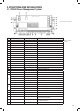
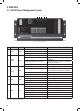
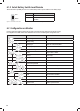
Figure 10 Front panel of PM435
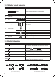
No. LABEL DEFINITION DESCRIPTION
1 Power AC input port
2 Switch panel Comm port Connect to switch panel
3 LCD Display Comm port Connect to Monitor
4 Battery switch Service battery switch Manual battery switch
5 )UHVKZDWHUWDQN &RQQHFWWRIUHVKZDWHUWDQN
6 )UHVKZDWHUWDQN &RQQHFWWRIUHVKZDWHUWDQN
7 7DSZDWHUWDQN &RQQHFWWRWDSZDWHUWDQN
8 :DVWHZDWHUWDQN &RQQHFWWRZDVWHZDWHUWDQN
9 Battery sensor For temp compensation Connect to service battery+
10 PV+ Solar input Connect to PV+
11 PV- Connect to PV-
12 Starter Bat+ Starter battery+ &RQQHFWWRVWDUWHUEDWWHU\9GF
13 Service Bat+ Service battery+ &RQQHFWWRVHUYLFHEDWWHU\9GF
14 Starter Bat- Starter battery- Connect to starter battery-
15 Service Bat- Service battery- Connect to service battery-
16 L1+ Step Connect to load of class D
17 L2+ ~ L3+ Connect to load of class C
18 L4+ ~ L6+ Connect to load of class B
19
L7+ Switch B Connect to Switch B+
L8+ Switch A Connect to Switch A+
L9+ Outside light Connect to Outside light+
L10+ TV Connect to TV+
L11+ Water pump Connect to Water pump+
20
L12+ Dining light Connect to Dining light+
L13+ Bedroom light Connect to Bedroom light+
L114+ Ceiling light Connect to Ceiling light+
21 L1- ~ L14- Connect to DC load -
22 D+ Point D+ input Connect to D+
23 Remote Switch 7HUPLQDOEORFN Connect to remote switch
24 Select Switch Dip switch Select local switch or remote switch (Notice: open the
XSSHUFRYHUERDUGWRRSHUDWH
25 Setting Dip switch Set the battery type and capacity (Notice: open the upper
FRYHUERDUGWRRSHUDWH
26 Fuse Fuses with indicator for blown
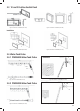
3. STRUCTURE AND INSTALLATION
3.1 PM400 Power Management System
Table 5 Connection
of PM435
1
3 4
5
6
7
8
9
25
2
26
10 11 12 13 14 15 16 17 18 19 20 21 22 2324