
Manual


14
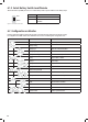
4.3 Preparation
PM400 system is designed with concept of ‘Plug in and Play’ in mind. To complete the easy installation, a screw driver and DC cables are
UHTXLUHG)ROORZ7DEOHUHFRPPHQGDWLRQIRUPLQLPXPZLULQJV
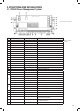
CURRENT MINIMUM CABLE SIZE
0–5A 1.0mm2 or 18 AWG
5–10A 2.0mm2 or 14 AWG
10–15A 3.0mm2 or 13 AWG
15–20A 4.0mm2 or 11 AWG
20–25A 5.0mm2 or 10 AWG
25–30A 6.0mm2 or 9 AWG
Table 7 Minimum cable size
4. WIRING
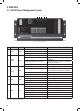
4.1 Material
)ROORZLQJFRPSRQHQWVDUHGHOLYHUHGWKH30SDFNDJH
CODE NAME MODEL OR
LENGTH
QTY. PART No. ON
DRAWING
1 Caravan Master Power PM435 11
2 Monitor with Bluetooth PMLCD-BT 12
3 10 Position Switch Panel PM4SW10 13
4 )UHVKZDWHUWDQNOHYHOVHQVRU
Not Included
04
5 )UHVKZDWHUWDQNOHYHOVHQVRU 05
6 7DSZDWHUWDQNOHYHOVHQVRU 06
7 :DVWHZDWHUWDQNOHYHOVHQVRU 07
8 2 Position Switch Panel PM4SW2 28
9 PV Not Included 09
10 Communication line – RS485 5m 1 PMLCDC
11 Switch panel line 5m 1 PM4SW10C
12 Battery sensor line 3m 1 PMBS
13 :DWHUWDQNSUREHOLQH
Not Included
0
PMWS200 /
PMWS400
14 :DWHUWDQNSUREHOLQH 0
15 :DWHUWDQNSUREHOLQH 0
16 :DWHUWDQNSUREHOLQH 0
17 Power Cable 1.5m 1 PMAC
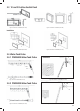
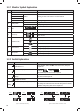
4.2 System Schematic
When running cables, if they pass through panels or wall, ensure the
cables are protected from damage by sharp edges. In such cases, it is
recommended to use cable glands.
Table 6 Component list of PM400
1
4 5 6 7
2
PMLCDC
PMAC
PM4SW10C
PMBS
PMTS
PMWS200/
PMWS400
PMWS200/
PMWS400
PMWS200/
PMWS400
PMWS200/
PMWS400
PM4SW2
3
8
9
PM435
Monitor
Flexi Panel 100W
10 Pos. Switch
2 Pos. Switch
Outdoor
Temperature Sensor
Battery Temperature
Sensor and Terminal
Voltage
AC in
240V / 50Hz
~
L
N
BM COM
Service Batt –
Service Batt +
Service Battery
(12VDC)
Starter Batt –
Starter Batt +
Starter Battery
(12VDC)
PV –
PV +
PV in
Vmp: 17–50V
DC cable, supplied by client
Fresh Water
Tank 1
Level Sensor
Fresh Water
Tank 2
Level Sensor
Tap Water
Tank
Level Sensor
Waste Water
Tank
Level Sensor
N L
AC IN
Monitor Switch
Panel
Battery
Sensor
Waste
Water
Tank
Tap
Water
Tank
Fresh
Water
Tank 2
Fresh
Water
Tank 1
•
L12
•
L13
•
L14
L14
•
L13
•
L12
•
L11
•
L10
•
L9
•
L8
•
L7
•
L6
•
L5
•
L4
•
L3
•
L2
•
L1
•
PV
• •
D + Input
Remote Switch
Service
Batt -
Service
Batt +
Starter
Batt -
Starter
Batt +
L11 L10 L9 L8 L7 L6 L5 L4 L3 L2 L1
• • • • • • • • • • •
Celing Light
Bedroom Light
Dining Light
Step
Refigerator
Load of Class C
Load of Class B
Load of Class B
Load of Class B
Switch B
Switch A
Outside Light
TV
Pump
D + Input