
Manual


15
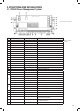
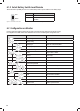
TYPE TERMINAL
MODEL NUMBER
SUITABLE CABLE
GAUGE
Type 1 ERTB10-10.16 0.5mm2 - 10mm2
Type 2 wago804-114 0.25mm2 - 2.5mm2
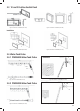
Figure 25 Connection of Terminal Type 1
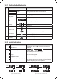
4.2 System Schematic
TYPE 1 TYPE 2
Figure 26 Connection of Terminal Type 2
1
4 5 6 7
2
PMLCDC
PMAC
PM4SW10C
PMBS
PMTS
PMWS200/
PMWS400
PMWS200/
PMWS400
PMWS200/
PMWS400
PMWS200/
PMWS400
PM4SW2
3
8
9
PM435
Monitor
Flexi Panel 100W
10 Pos. Switch
2 Pos. Switch
Outdoor
Temperature Sensor
Battery Temperature
Sensor and Terminal
Voltage
AC in
240V / 50Hz
~
L
N
BM COM
Service Batt –
Service Batt +
Service Battery
(12VDC)
Starter Batt –
Starter Batt +
Starter Battery
(12VDC)
PV –
PV +
PV in
Vmp: 17–50V
DC cable, supplied by client
Fresh Water
Tank 1
Level Sensor
Fresh Water
Tank 2
Level Sensor
Tap Water
Tank
Level Sensor
Waste Water
Tank
Level Sensor
N L
AC IN
Monitor Switch
Panel
Battery
Sensor
Waste
Water
Tank
Tap
Water
Tank
Fresh
Water
Tank 2
Fresh
Water
Tank 1
•
L12
•
L13
•
L14
L14
•
L13
•
L12
•
L11
•
L10
•
L9
•
L8
•
L7
•
L6
•
L5
•
L4
•
L3
•
L2
•
L1
•
PV
• •
D + Input
Remote Switch
Service
Batt -
Service
Batt +
Starter
Batt -
Starter
Batt +
L11 L10 L9 L8 L7 L6 L5 L4 L3 L2 L1
• • • • • • • • • • •
Celing Light
Bedroom Light
Dining Light
Step
Refigerator
Load of Class C
Load of Class B
Load of Class B
Load of Class B
Switch B
Switch A
Outside Light
TV
Pump
D + Input
Figure 23 System Schematic
4.4 Connection
PM400 unit is designed with a spring and screw terminal. Please refer to following illustration at right.
(DFKW\SHRIWHUPLQDOLVGHVLJQHGWRõWDGLIIHUHQWUDQJHRIFDEOHV
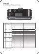
Table 8 Recommended terminal and cable gauge Figure 24 PM435 Terminal
Type 1 Type 2