
Manual


16
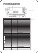
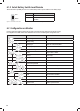
No. LED COLOUR STATUS DESCRIPTION
1 Mains GREEN
ON AC input OK
OFF AC disconnected
4XLFNöDVKLQJöDVKWZLFHHYHU\VHFRQG AC input abnormal
2
Starter
Battery
GREEN
ON Alternator charging the SERVICE battery
6ORZöDVKLQJöDVKRQFHHYHU\VHFRQG Starter battery is >13.4V and is being charged by
the PM435
4XLFNöDVKLQJöDVKWZLFHHYHU\VHFRQG The Starter Battery is 2~13.4V or >16.0V, while
AC power is connected.
OFF Starter battery is disconnected.
3
PV
6RODU
GREEN
ON Solar charging the battery
6ORZöDVKLQJöDVKRQFHHYHU\VHFRQG The input voltage of the Solar is normal and the
service battery is charged by the AC or Alternator
4XLFNöDVKLQJöDVKWZLFHHYHU\VHFRQG PV input error
OFF PV disconnected
4 &+* GREEN
ON Battery charged
)ODVKLQJöDVKRQFHHYHU\VHFRQG Battery charging
6ORZöDVKLQJVHFRQGRQVHFRQGVRII Battery discharge
OFF Battery disconnected
5 FAULT RED
ON Short circuit
Flash once per cycle Service battery voltage low
Flash twice per cycle Service battery voltage high
Flash 3 times per cycle PM435 unit Over Temperature
Flash 4 times per cycle %XONFKDUJHWLPHRXW
Flash 5 times per cycle VCR anomaly
Flash 6 times per cycle Environment Over Temperature
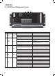
Figure 27 An overview of PM435
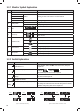
5. DISPLAY
5.1 PM400 Power Management System
P/No. PM335
Table 9 LED indicator description of PM435
1 2 3 4 5